转载https://www.sohu.com/a/445372856_657867
其实堆叠吧,也算是一种虚拟化技术了。你可以理解为把多台交换机虚拟化成一台大的交换机去使用。

本期就与大家分享一下如何用H3C模拟器(HCL)来配置交换机irf。
01
实验环境搭建
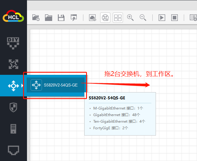
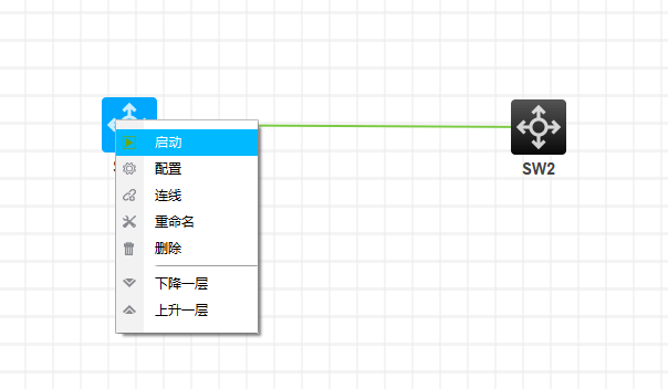
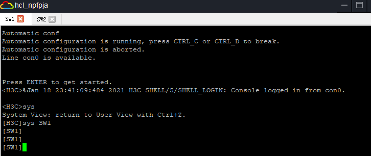
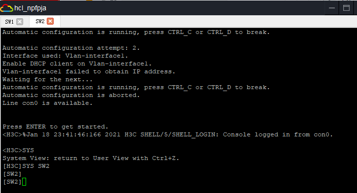
接下来,分别启动两台交换机
02
基础配置
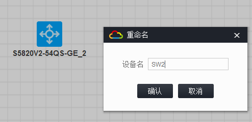
分别给每台交换机修改设备名(这个不是必须的配置,我是为了给大家演示一下,作完堆叠后,SW2设备名也会自动更改)
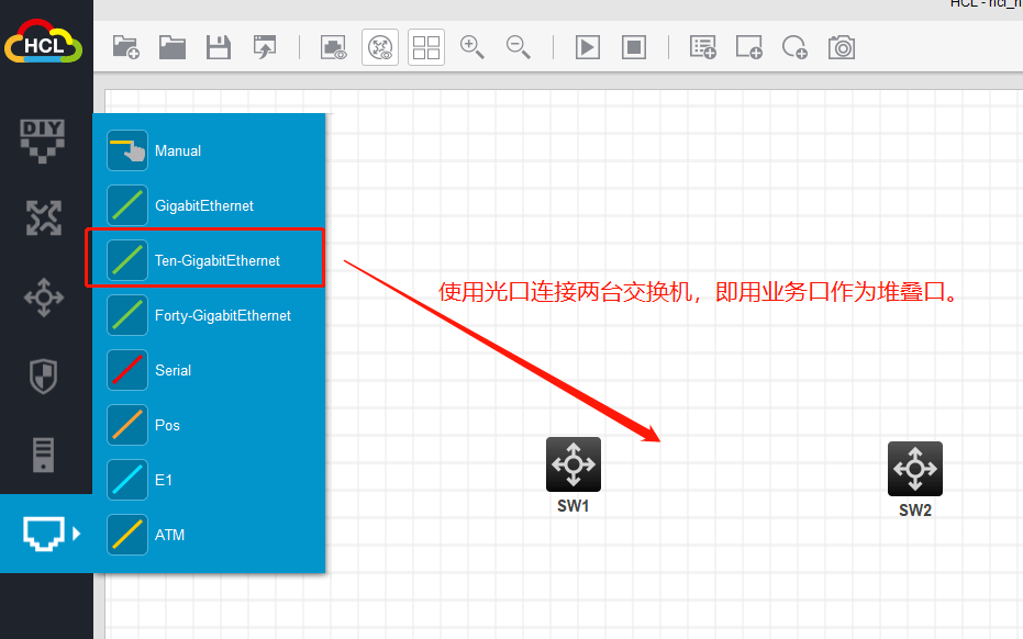
先将互联的接口shutdown一下:
[SW1]int Ten-GigabitEthernet 1/0/49
[SW1-Ten-GigabitEthernet1/0/49]shut
[SW1-Ten-GigabitEthernet1/0/49]quit
[SW1]
[SW2]int Ten-GigabitEthernet 1/0/49
[SW2-Ten-GigabitEthernet1/0/49]shut
[SW2-Ten-GigabitEthernet1/0/49]quit
[SW2]
03
irf堆叠关键配置
[SW1]irf domain 100
[SW1]irf member 1 renumber 1
Renumbering the member ID may result in configuration change or loss. Continue?[Y/N]:y
[SW1]
[SW1]irf-port 1/1
[SW1-irf-port1/1]port group interface Ten-GigabitEthernet 1/0/49
[SW1-irf-port1/1]quit
[SW1]
[SW1]irf-port-configuration active
[SW2]irf domain 100
[SW2]irf member 1 renumber 2
Renumbering the member ID may result in configuration change or loss. Continue?[Y/N]:y
[SW2]
[SW2]irf-port 1/2
[SW2-irf-port1/2]port group interface Ten-GigabitEthernet 1/0/49
[SW2-irf-port1/2]quit
[SW2]
[SW2]irf-port-configuration active
解释:irf member 1 renumber 2
这个就是把原来接口卡编号重新规划命名,两台交换机不能一样。
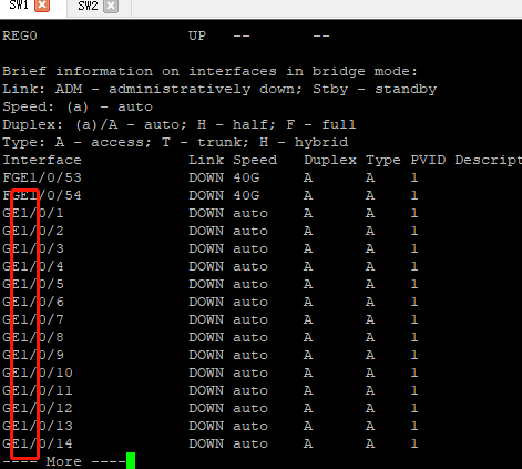
irf member 1 renumber 2,即把上图红色圈起来的接口卡编号由1改为2.
由于SW1是1,那SW2需要区别开,所以改成2,当然你也可以改成其他的,一般建议数字连续吧。
04
保存,重启,堆叠生效
现在我们把接口打开undo shutdown一下:
[SW1]int Ten-GigabitEthernet 1/0/49
[SW1-Ten-GigabitEthernet1/0/49]undo shut
[SW1-Ten-GigabitEthernet1/0/49]quit
[SW1]
[SW2]int Ten-GigabitEthernet 1/0/49
[SW2-Ten-GigabitEthernet1/0/49]undo shut
[SW2-Ten-GigabitEthernet1/0/49]quit
[SW2]
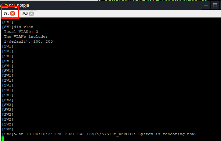
堆叠生效之前,我们来做个小测试,在SW1,创建vlan 100,然后在SW2查看:
SW2上未看到vlan 100,只有默认VLAN1:
接下来,记得保存一下再重启,观察堆叠是否生效了:
<SW1>save
The current configuration will be written to the device. Are you sure? [Y/N]:y
Please input the file name(*.cfg)[flash:/startup.cfg]
(To leave the existing filename unchanged, press the enter key):
Validating file. Please wait...
Saved the current configuration to mainboard device successfully.
<SW1>reboot
Start to check configuration with next startup configuration file, please wait.........DONE!
This command will reboot the device. Continue? [Y/N]:Y
Now rebooting, please wait...
%Jan 19 00:08:30:352 2021 SW1 DEV/5/SYSTEM_REBOOT: System is rebooting now.
<SW2>save
The current configuration will be written to the device. Are you sure? [Y/N]:y
Please input the file name(*.cfg)[flash:/startup.cfg]
(To leave the existing filename unchanged, press the enter key):
Validating file. Please wait...
Saved the current configuration to mainboard device successfully.
<SW2>reboot
Start to check configuration with next startup configuration file, please wait.........DONE!
This command will reboot the device. Continue? [Y/N]:Y
Now rebooting, please wait...
%Jan 19 00:06:31:073 2021 SW2 DEV/5/SYSTEM_REBOOT: System is rebooting now.
05
验证查看
重启后,你会发现SW2的设备名自动修改为SW1了:
也间接说明堆叠配置成功了,我们也可以查一下堆叠状态:

现在我们可以在SW1创建一个vlan 200,看看原先所谓的SW2是不是也自动看到这个配置:
在原先SW2 可以看到这个配置了:
到这里,堆叠就基本配置完成了。
06
修改irf优先级可改变master
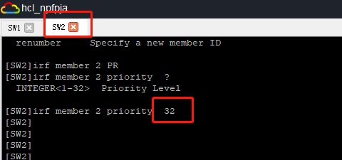
在原先sw2上修改设备名:

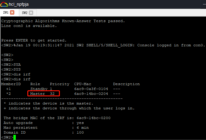
在原先sw2上修改irf优先级,比如这里修改到最高32:
在原先sw2那台保存配置,重启生效:
<SW2>save
The current configuration will be written to the device. Are you sure? [Y/N]:Y
Please input the file name(*.cfg)[flash:/startup.cfg]
(To leave the existing filename unchanged, press the enter key):
flash:/startup.cfg exists, overwrite? [Y/N]:Y
Validating file. Please wait...
Saved the current configuration to mainboard device successfully.
Slot 2:
Save next configuration file successfully.
<SW2>
<SW2>reboot
Start to check configuration with next startup configuration file, please wait.........DONE!
This command will reboot the device. Continue? [Y/N]:Y
Now rebooting, please wait...
%Jan 19 00:18:24:890 2021 SW2 DEV/5/SYSTEM_REBOOT: System is rebooting now.
SW1自动重启:
重启后,你会发现原先SW2那台变成Master了,所以优先级高的,就是Master:
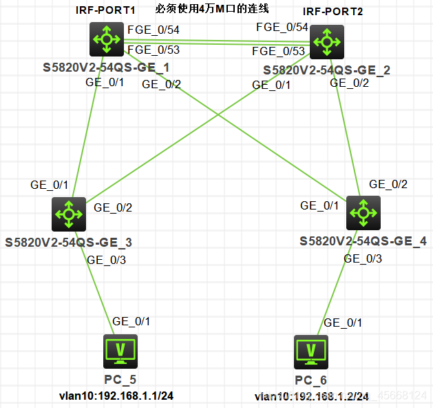
二台交换机堆叠
1.二台交换机的堆叠实验拓扑
irf区域设置为10,IRFSW1为member 1,优先级设置为10;IRFSW2为member 2,优先级保持默认 1,最大的优先级为32.
实验配置及命令
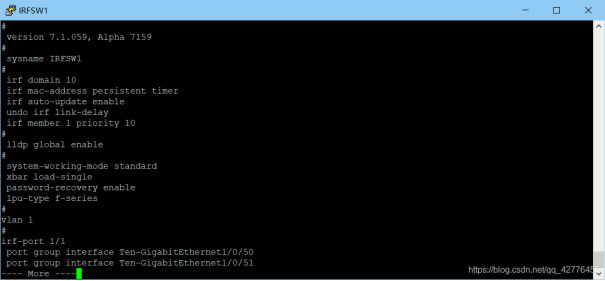
IRFSW1:
irf 区域设置,并设置member 1的优先级。(默认编号也是1,最大是32)
[IRFSW1]irf domain 10
[IRFSW1]irf member 1 priority 10
先关闭端口,然后创建irf-port 1/1(member号/逻辑口编号),然后将物理口加入,再开启刚关闭的端口。
[IRFSW1]interface range FastEthernet 1/0/53 to FastEthernet1/0/54
[IRFSW1-if-range]shutdown
[IRFSW1]irf-port 1/1
[IRFSW1-irf-port1/1]port group interface FastEthernet 1/0/53
[IRFSW1-irf-port1/1]port group interface FastEthernet 1/0/54
[IRFSW1]interface range FastEthernet 1/0/53 to FastEthernet1/0/54
[IRFSW1-if-range]undo shutdown
配置结果
IRFSW2:
更改成员编号后需要保存配置后,重启使其生效。次时端口号变为2/0/50,2/0/51…
[IRFSW2]irf domain 10
[IRFSW2]irf member 1 renumber 2
<IRFSW2>save
The current configuration will be written to the device. Are you sure? [Y/N]:y
Please input the file name(*.cfg)[flash:/startup.cfg]
(To leave the existing filename unchanged, press the enter key):
Validating file. Please wait...
Saved the current configuration to mainboard device successfully.
<IRFSW2>reboot
这步和IRFSW1差不多,但是有一点很重要,特别是对多层堆叠:
irf-port 后面跟的1/1,2/2不是随便弄的,前者(数字)是交换机的成员编号,后者是成员编号对应的逻辑口号,每台只有1,2两个,你可以是n/1,n/2,但是如果你是n/1的话,那你下一个就只能是n+1/2,如果是n/2就和n/1配对,不可以两个都是1或者都是2。
[IRFSW2]interface range FastEthernet 2/0/53 to FastEthernet 2/0/54
[IRFSW2-if-range]shutdown
[IRFSW2]irf-port 2/2
[IRFSW2-irf-port2/2]port group interface FastEthernet 2/0/53
[IRFSW2-irf-port2/2]port group interface FastEthernet 2/0/54
[IRFSW2]interface range FastEthernet 2/0/53 to FastEthernet 2/0/54
[IRFSW2-if-range]undo shut
[IRFSW2-if-range]undo shutdown
配置结果

启动配置:
[IRFSW2]irf-port-configuration active
<IRFSW2>reboot
<IRFSW1>reboot

成功以后每台设备的名称会自动变成主设备的名称。
二.配置了堆叠后的设备链路验的配置
SW1]dis irf
MemberID    Role    Priority  CPU-Mac         Description
  *1        Master  1         2e92-6b04-0104  ---
  +2        Standby 1         2e92-832c-0204  ---
-
IRF-SW的配置链路聚合
链路聚合先配置物理端口加入聚合组,再做聚合组vlan、trunk划分等设置。
//在IRF-SW上配置,将SW1的g0/1与SW2的g0/1做聚合
[IRF-SW]interface Bridge-Aggregation 1 //创建聚合口[TRF-SW1]port link-type trunk //接口类型配置为Trunk
[TRF-SW1]port trunk permit vlan 10 //Trunk接口允许VLAN10通过[IRF-SW-Bridge-Aggregation1]int g1/0/1 //进入物理接口(第一台核心交换机的物理接口)
[IRF-SW-GigabitEthernet1/0/1]port link-aggregation group 1 //将物理接口加入聚合口
[IRF-SW-GigabitEthernet1/0/1]int g2/0/1 //进入物理接口(第二台核心的物理接口因为是做了堆叠修改为了是2/0/1开头的)
[IRF-SW-GigabitEthernet2/0/1]port link-aggregation group 1 //将物理接口加入聚合口
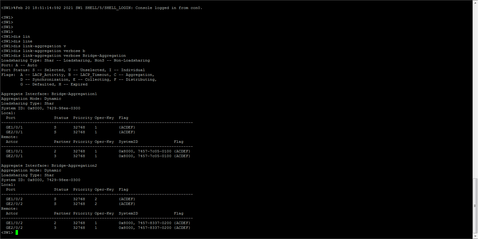
[IRF-SW-GigabitEthernet2/0/1]display link-aggregation summary //检查两个端口是否都被加入到聚合口,简写dis link-a su //同样方法将SW1的g0/2与SW2的g0/2做聚合
//在IRF-SW上配置,将SW1的g0/1与SW2的g0/1做聚合

[IRF-SW]interface Bridge-Aggregation 2 //创建聚合口[TRF-SW1]port link-type trunk //接口类型配置为Trunk
[TRF-SW1]port trunk permit vlan 10 //Trunk接口允许VLAN10通过[IRF-SW-Bridge-Aggregation1]int g1/0/2 //进入物理接口(第一台核心交换机的物理接口)
[IRF-SW-GigabitEthernet1/0/2]port link-aggregation group 1 //将物理接口加入聚合口
[IRF-SW-GigabitEthernet1/0/2]int g2/0/2 //进入物理接口(第二台核心的物理接口因为是做了堆叠修改为了是2/0/1开头的)
[IRF-SW-GigabitEthernet2/0/2]port link-aggregation group 1 //将物理接口加入聚合口
[IRF-SW-GigabitEthernet2/0/2]display link-aggregation summary //检查两个端口是否都被加入到聚合口,简写dis link-a su
接入层的交换机配置
- SW3把连接与核心交换机的接口加入VLAN10(配置trunk模式)
在SW3上将g0/1与g0/2做聚合
[SW3]int Bridge-Aggregation 1
[SW3]int Bridge-Aggregation 1  //创建聚合口
[SW3-Bridge-Aggregation1]port link-type trunk   //接口类型配置为Trunk
[SW3-Bridge-Aggregation1]port trunk permit vlan 10  //Trunk接口允许VLAN10通过
[SW3-Bridge-Aggregation1]int g1/0/1
[SW3-GigabitEthernet1/0/1]port link-aggregation group 1
[SW3-Bridge-Aggregation1]int g1/0/2
 [SW3-GigabitEthernet1/0/2]port link-aggregation group 1
[SW3-GigabitEthernet1/0/2]qu //同样方法在SW4上将g0/1与g0/2做聚合
- SW3把连接PC的接口加入VLAN10
[SW3]vlan 10
[SW3-vlan10]port g1/0/3
[SW3-vlan10]qu

//同样方法将SW4接PC端的接口划分到VLAN10
- 将SW4与核心交换机聚合端口配置为Trunk类型
[SW3]int Bridge-Aggregation 2 //创建聚合口
[SW3-Bridge-Aggregation1]port link-type trunk   //接口类型配置为Trunk
[SW3-Bridge-Aggregation1]port trunk permit vlan 10  //Trunk接口允许VLAN10通过
[SW3]dis link-aggregation summary  /检查聚合口

//同样方法将SW4聚合端口配置为Trunk类型

//在IRF-SW上将两个聚合口均配置为Trunk类型,并配置放行VLAN10

[IRF-SW]vlan 10  //划分VLAN10
[IRF-SW]int Bridge-Aggregation 2  //进入1聚合接口
[IRF-SW-Bridge-Aggregation1]port link-type trunk   //聚合接口1配置为Trunk类型
[IRF-SW-Bridge-Aggregation1]port trunk permit vlan 10  //放行VLAN10
[IRF-SW-Bridge-Aggregation1]qu
[IRF-SW]dis link-aggregation summary  //检查聚合接口
- SW4把连接PC的接口加入VLAN10
[SW3]vlan 10
[SW3-vlan10]port g1/0/3
[SW3-vlan10]qu
转载https://www.cnblogs.com/bawxfiw/p/14243588.html