1 Scenarios
Two scenarios for passing signals across CDC boundaries:
1) sometimes it's not necessary to sample every value, but be sure that the sampled values are accurate. One example is the set of gray
code counters used in asynchronous FIFO. In asynchronous FIFO, synchronized gray code counters do not need to capture every legal value from
the opposite clock domain, but it's critical that sampled values be accurate to recognize when full and empty conditions have occurred.
2) a CDC signal must be properly recognized or recognized & acknowledged before a change occurs.
In both of these scenarios, the CDC signals will require some form of synchronization into the receiving clock domain.
2 Receiving clock domain
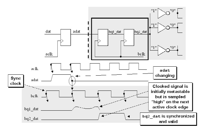
1) Two flip-flop synchronizer
For most synchronization applications, the two flip-flop synchronizer is sufficient to remove all likely metastability.

2) Three flip-flop synchronizer
For some very high speed designs, a third flop is added to increase the MTBF to a satisfactory duration of time.

3 Sending clock domain
Registering signals in the sending clock domain should generally be required.

4 Example (Verilog)
 1 module  sync_cell (
 2
 3 // OUTPUTs
 4     data_out,                      // Synchronized data output
 5
 6 // INPUTs
 7     clk,                           // Receiving clock
 8     data_in,                       // Asynchronous data input
 9     rst                            // Receiving reset (active high)
10 );
11
12 // OUTPUTs
13 output              data_out;      // Synchronized data output
14
15 // INPUTs
16 input               clk;          // Receiving clock
17 input               data_in;      // Asynchronous data input
18 input               rst;          // Receiving reset (active high)
19
20
21 //=================================================
22 // 1)  SYNCHRONIZER
23 //=================================================
24
25 reg  [1:0] data_sync;
26
27 always @(posedge clk or posedge rst)
28   if (rst) data_sync <=  2'b00;
29   else     data_sync <=  {data_sync[0], data_in};
30
31 assign     data_out   =   data_sync[1];
32
33
34 endmodule // sync_cell