https://github.com/Apress/physically-based-shader-dev-for-unity-2017
Part I: Introduction to Shaders In Unity
Chapter 1: How Shader Development Works (已看)
Chapter 2: Your First Unity Shader (已看)
Chapter 3: The Graphics Pipeline (已看)
Chapter 4: Transforming Coordinate Spaces (已看)
Chapter 5: Your First Unity Lighting Shader (已看)
Chapter 6: Specular Implementation (已看)
Part II: Physically Based Shading
Chapter 8: What Is Physically Based Shading?
Chapter 9: Making a Shader Physically Based
Chapter 10: Post-Processing Effects
Chapter 12: Implementing a BRDF
Chapter 13: Hooking Into the Standard Shader
Chapter 14: Implementing Advanced Techniques
Part III: Shader Development Advice
Chapter 15: Making Shaders Artists Will Use
Chapter 16: Complexity and Ubershaders
Chapter 17: When Shading Goes Wrong
Chapter 18: Keeping Up with the Industry
Chapter 1: How Shader Development Works
What Is a Shader?
Going straight to the heart of the matter, a shader is both:
- A simulation made in code of what happens at the surface microscopic level, which makes the final image look realistic to our eyes
- A piece of code that runs on GPUs
Shaders as Light Simulations
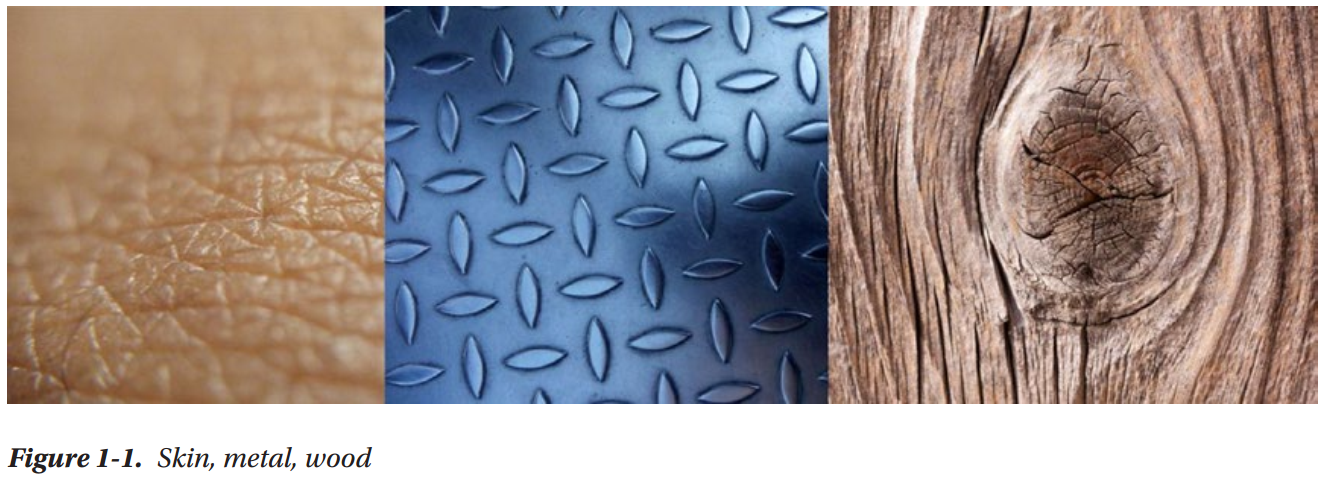
Your brain can instantly understand what material an object is made of, just by looking at it. That happens because every material’s pattern of interaction with light is very characteristic and recognizable to the human brain. Lighting shaders simulate that interaction with light, either by taking advantage of what we know about the physics of light, or through a lot of trial and error and effort from the artists
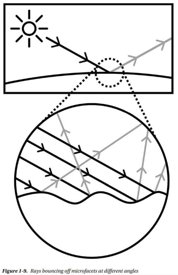
In the physical world, surfaces are made of atoms, and light is both a wave and a particle. The interaction between light, the surface, and our eyes determines what a surface will look like. When light coming from a certain direction hits a surface, it can be absorbed, reflected (in another direction), refracted (in a slightly different direction), or scattered (in many different directions). The behavior of light rays, when they come in contact with a surface, is what creates the specific look of a material

Even if a surface looks smooth at the macroscopic level, like skin does, at the microscopic level, it can have micro-facets that scatter light in different directions
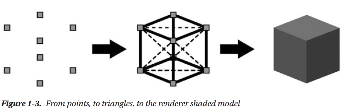
Inside computers we don't have the computational power needed to simulate reality to that level of detail. If we had to simulate the whole thing, atoms and all, it would take years to render anything. In most renderers, surfaces are represented as 3D models, which are basically points in 3D space (vertices) at a certain position, that are then grouped in triangles, which are then again grouped to form a 3D shape. Even a simple model can have thousands of vertices
Our 3D scene, composed of models, textures, and shaders, is rendered to a 2D image, composed of pixels. This is done by projecting those vertex positions to the correct 2D positions in the final image, while applying any textures to the respective surfaces and executing the shaders for each vertex of the 3D models and each potential pixel of the final image
This is what physically based rendering is all about. It's basically a catalog of various types of lighting behaviors in surfaces and the mathematical models we use to approximate them
Rendering as Perspective Drawing
Rendering is conceptually (and mathematically) very similar to the painter’s process of drawing from life, into a canvas, using perspective.
The techniques of perspective drawing originated in the Italian Renaissance, more than 500 years ago, even if the mathematical foundations for it were laid much earlier, back in Euclid’s times. In our case, the canvas is our final image, the scene and 3D models are reality, and the painter is our renderer.
In computer graphics, there are many ways to render the scene, some more computationally expensive and some less. The fast type (rasterizer-based) is what real-time rendering, games included, has been using. The slow type (raytracing, etc.) is what 3D animated movies generally use, because rendering times can reach even hours per frame.
The rendering process for the fast type of renderers can be simplified like so: first the shapes of the models in the scene are projected into the final 2D image; let’s call it the “sketching the outline” phase, from our metaphorical painter’s point of view. Then the pixels contained within each outline are filled, using the lighting calculations implemented in the shaders; let’s call that the “painting” phase.
You could render an image without using shaders, and we used to do so. Before the programmable graphics pipeline, rendering was carried out with API calls (APIs such as OpenGL and DirectX3D). To achieve better speed, the APIs would give you pre-made functions, to which you would pass arguments. They were implemented in hardware, so there was no way to modify them. They were called fixed-function rendering pipelines.
To make renderers more flexible, the programmable graphics pipeline was introduced. With it, you could write small programs, called shaders, that would execute on the GPU, in place of much of the fixed-function functionality
Rendering Process
As mentioned, this type of rendering could be conceptually broken down in two phases:
- The outline phase
- The painting phase
The outline phase determines which pixels in the final image are going to belong to a certain triangle, by projecting the vertices of the models into the final image, and checking for whether another model is in front, from the camera’s point of view. The painting phase calculates the color of each pixel, according to the scene data (lights, textures, and lighting calculations).
The first phase manipulates vertices, the second phase manipulates the information it gets from the first phase and outputs the pixel colors.
Shaders as Code Running on GPUs
As mentioned, there can be many thousands of vertices in a model, and a rendered image can have millions of pixels. Typically a shader will run on every vertex in the scene, and on every pixel in the final image. To achieve that real-time rendering speed, we need a special processor that’s capable of running very short programs millions of times in just milliseconds. Such a processor is a commonly known as a Graphics Processing Unit, or GPU.
Shading is a dataflow process in one direction, which means that vertices, textures, and shaders enter, and then, at the other end, colors exit, and are put into a render target, meaning basically a 2D image. We don’t need to know anything about the vertices near the one we’re processing, or the pixels near the one we’re calculating (at least most of the time), hence all those shaders can be executed independently, at the same time, on a large number of vertices/pixels.
Shader Execution
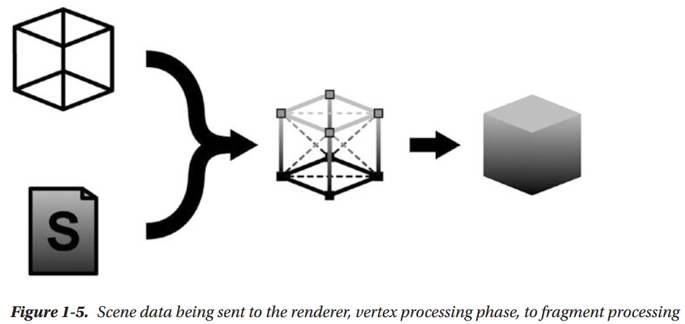
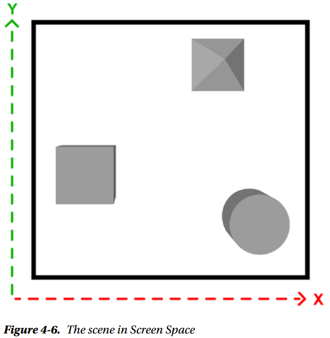
This scene has eight vertices, and it has been rendered to a 1920x1080 image (full HD resolution). What is happening exactly in the rendering process?
1. The scene’s vertices and their respective data are passed to the vertex shader.
2. A vertex shader is executed on each of them.
3. The vertex shader produces an output data structure from each vertex, containing information such as color and position of the vertex on the final image.
4. Sequences of vertices are assembled into primitives, such as triangles, lines, points, and others. For the purposes of this book, we'll assume triangles.
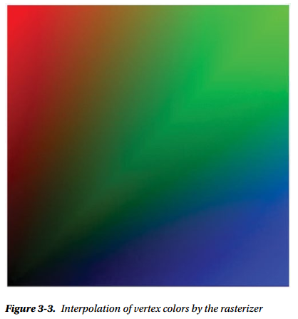
5. The rasterizer takes a primitive and transforms it into a list of pixels. For each potential pixel within that triangle, that structure’s values are interpolated and passed to the pixel shader. (For example, if one vertex is green, and an adjacent vertex is red, the pixels between them will form a green to red gradient.) The rasterizer is part of the GPU; we can’t customize it.
6. The fragment shader is run for any potential pixel. This is the phase that will be more interesting for us, as most lighting calculations happen in the fragment shader.
7. If the renderer is a forward render, for every light after the first, the fragment shader will be run again, with that light’s data.
8. Each potential pixel (aka, fragment) is checked for whether there is another potential pixel nearer to the camera, therefore in front of the current pixel. If there is, the fragment will be rejected.
9. All the fragment shader light passes are blended together.
10. All pixel colors are written to a render target (could be the screen, or a texture, or a file, etc.)
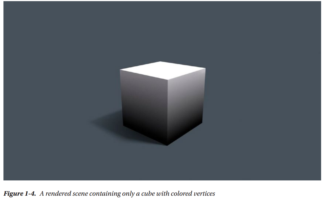
As you can see in Figure 1-5, this cube has colored vertices. The gradient from black to gray in the shaded cube is due to the interpolation happening in Step 4
Different Types of Shaders
We have already mentioned a couple types of shaders. Here they are and a few more:
Vertex shader: Executed on every vertex.
Fragment shader: Executed for every possible final pixel (known as a fragment).
Unlit shader: Unity-only, a shader that combines a vertex and pixel shader in one file.
Surface shader: Unity-only, contains both vertex and fragment shader functionality, but takes advantage of the ShaderLab extensions to the Cg shading language to automate some of the code that’s commonly used in lighting shaders.
Image Effect shader: Unity-only, used to apply effects like Blur, Bloom, Depth of Field, Color Grading, etc. It is generally the last shader run on a render, because it’s applied to a render of the geometry of the scene.
Compute shader: Computes arbitrary calculations, not necessarily rendering, e.g., physics simulation, image processing, raytracing, and in general, any task that can be easily broken down into many independent tasks. In this book, we spend a fair amount of time
on Unity surface shaders, but we won’t cover compute shaders. There are even more types of shaders, but since they are not used as often, we won’t mention them
Coordinate Systems
Every calculation in a shader lives in a particular coordinate system.
- Local (or Object) Space: The 3D coordinate system relative to the model being rendered
- World Space: The 3D coordinate system relative to the entire scene being rendered
- View (or Eye) Space: The 3D coordinate system relative to the viewer’s point of view (the camera you’re rendering from)
- Clip Space: A 3D coordinate system that has a range of -1.0 to 1.0
- Screen Space: The 2D coordinate system relative to the render target (the screen, etc.)
- Tangent Space: Used in Normal Mapping
Various phases of the rendering pipeline translate between two spaces, in order to execute the calculation in the most appropriate space. Choosing the right coordinate system can make calculations simpler and computationally cheaper.
Types of Light
In nature, every light is emitted from a 3D surface. There is no such thing as a real-life pixel. In rendering, we use approximations to reduce the computing power needed, but those approximations can limit the fidelity of our rendering.
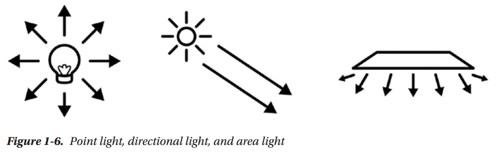
Point Light
Think of a night lamp, which is a small light that sends rays all around, but those rays don’t reach very far. Point lights have a falloff, meaning at a certain distance, the light fades off completely
Directional Light
Think of the sun; it’s so far away from us, that even if it is a point light, all the rays that reach us are parallel. If you were to zoom in on the light of a point light very very near, you would get to a point where the visible rays are all parallel. As a consequence, we're not going to reach the falloff, thus a directional light goes on infinitely.
Area Light
Area light is the best approximation of the three for physical reality, but more expensive computationally. Any real object that emits light will most likely be tridimensional, and therefore have an area. But that complicates the rendering calculations making them more expensive. Unity doesn’t have an area light usable for real-time lighting; it can only be used when baking lightmap
The Rendering Equation
The Behavior of Light
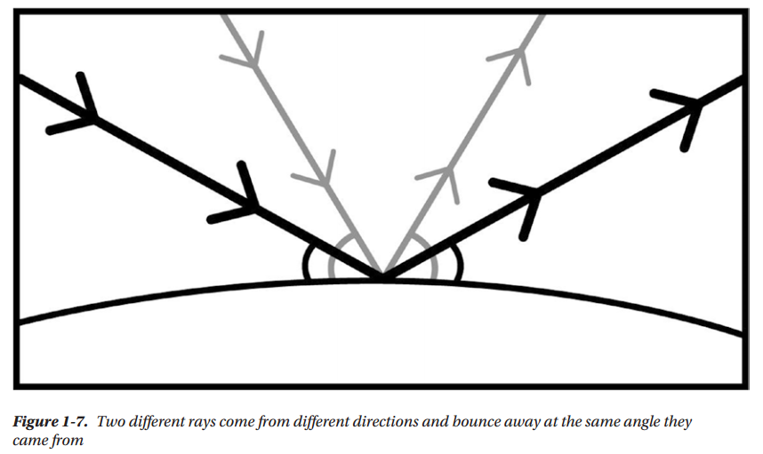
Everything that we see, we see because some light has hit that object and it has bounced off of it, in the direction of our eyes. Exactly how and why that bouncing happens is very important to rendering. How much light will bounce off a surface, and in which directions, depends on many factors:
The angle the light ray is coming from (aka, reflection). The more parallel it is, the less it will bounce
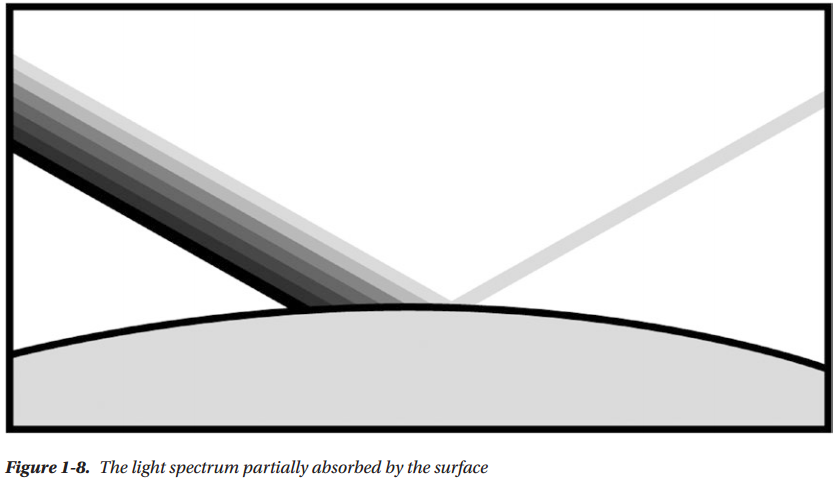
The color of the surface (aka, absorption). The light spectrum includes all visible colors. A red surface will absorb all other colors in the spectrum, and only reflect the red portion.
The smoothness or roughness of the surface. At the microscopic level, surfaces can be rougher than they look, and microfacets can bounce light in different directions.
Semitransparent layers. Think of a puddle. The ground under it looks darker than dry ground, because the water surface is reflecting some light off, thus allowing less light to reach the ground.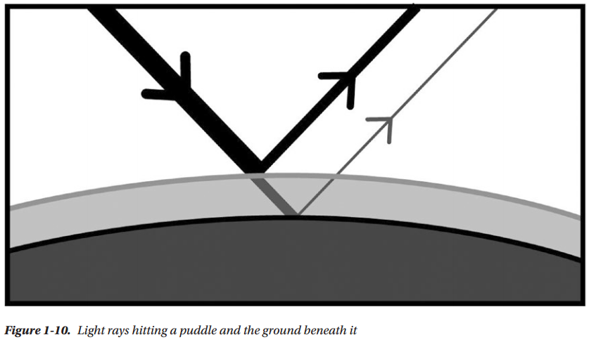
Bounced Light
As you might imagine, the light that is reflected off of one surface often ends up hitting another surface, which again is going to reflect some part of it. Bounced light will keep bouncing until the energy is completely used up. That is what global illumination simulates.
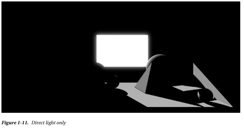
The light that hits a surface directly is called direct light; the light that hits the object after bouncing off from another surface is called indirect light.
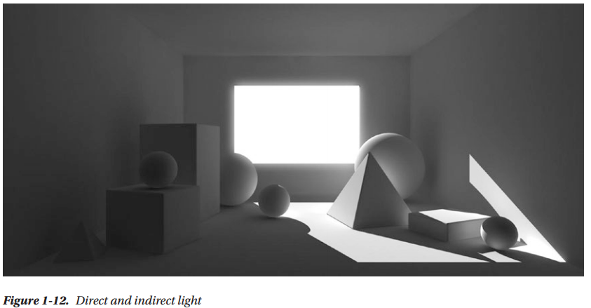
Before 2010, games generally used a very crude approximation of global illumination, such as ambient light, which consisted of only one value for the entire scene. Spherical harmonics are also used to approximate GI. They are a more faithful approximation than ambient, but more expensive and more mathematically complex as well.
Renderer Type
There are a few types of renderers, and many hybrids between them. Depending on the art direction of a game, certain parts of the scene will take more time to render compared to others. From that, comes the need to change the renderer, in order to optimize the more time-consuming parts
Forward
This is the first type of real-time renderer. It used to be implemented within the Graphics API (OpenGL or Directx3D). It is the type we’ve talked about until now. The scene information is fed into it, every triangle is rasterized, and for each light, there is a shading pass.
Deferred
Without global illumination, the only way to render more natural scenes was using a large number of lights. This started to be common practice in the PS3/Xbox360 generation. But, as you know, every additional light in a Forward renderer means an extra shader pass on all pixels.
To achieve better performance, this new type of renderer was invented, which would defer the shading of the scene to the last possible moment. That allows it to ignore the lights that are not reaching the model being shaded at the moment, which makes for much better performance.
Deferred renderers have some problematic spots, such as the impossibility of rendering transparent objects properly. They are also less flexible, because the information passed onto the shading phase has to be decided beforehand, while developing the renderer.
Forward+(Tiled Forward Shading)
In the PS4/Xbox One generation, various approximations of global illumination are possible, which makes Deferred less attractive. A mix of Forward and Deferred, this renderer type breaks the image into tiles, which are shaded with the Forward method, but only considering the lights that are influencing the current tile. This renderer type is not available in Unity at the moment
Future Renderers
The industry seems to be going toward developing more flexible renderers that can be better customized for the needs of each game. Unity is already working on a scriptable render loop, which will allow you to write the rendering code itself, while at the moment you can only choose between Forward and Deferred. This new functionality is already available in the current Unity betas
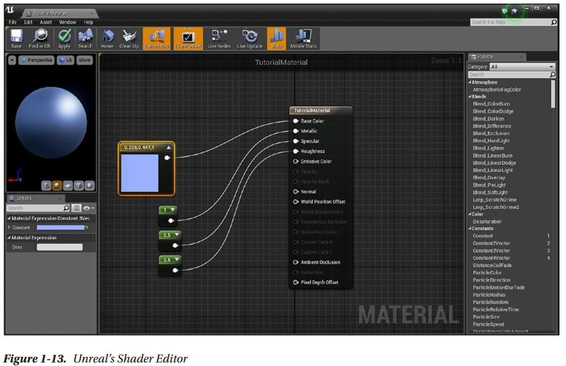
Shader Visual Graphs
Summary
Next
Chapter 2: Your First Unity Shader
Introduction to Unity
Set Up
Unity UI
Make Your First Scene
Shader Editing


Shader "Unlit/RedShader"
{
    Properties
    {
        _MainTex ("Texture", 2D) = "white" {}
    }
    SubShader
    {
        Tags { "RenderType"="Opaque" }
        LOD 100

        Pass
        {
            CGPROGRAM
            #pragma vertex vert
            #pragma fragment frag
            // make fog work
            #pragma multi_compile_fog

            #include "UnityCG.cginc"

            struct appdata
            {
                float4 vertex : POSITION;
                float2 uv : TEXCOORD0;
            };

            struct v2f
            {
                float2 uv : TEXCOORD0;
                UNITY_FOG_COORDS(1)
                float4 vertex : SV_POSITION;
            };

            sampler2D _MainTex;
            float4 _MainTex_ST;

            v2f vert (appdata v)
            {
                v2f o;
                o.vertex = UnityObjectToClipPos(v.vertex);
                o.uv = TRANSFORM_TEX(v.uv, _MainTex);
                UNITY_TRANSFER_FOG(o,o.vertex);
                return o;
            }

            fixed4 frag (v2f i) : SV_Target
            {
                // sample the texture
                fixed4 col = tex2D(_MainTex, i.uv);
                // apply fog
                UNITY_APPLY_FOG(i.fogCoord, col);
                return col;
            }
            ENDCG
        }
    }
}
Path and Name of the Shader
Shader "Unlit/RedShader"
Properties
Properties
    {
        _MainTex("Texture", 2D) = "white" {}
    }
Each property that shows up in the inspector is declared here, plus some that don’t need to be declared.
Sub-Shaders
SubShader
{
There can be more than one sub-shader in a shader, and there are a few types of them. When loading the shader, Unity will use the first sub-shader that’s supported by the GPU. Each sub-shader contains a list of rendering passes.
Tags
Tags { "RenderTpe" = "Opaque" }
Tags are key/value pairs that can express information, like which rendering queue to use. Transparent and opaque GameObjects are rendered in different rendering queues, which is why the code is specifying “Opaque”
Passes
Pass
{
Each pass contains information to set up the rendering and the actual shader calculations code. Passes can be executed one by one, separately, from a C# script
CGPROGRAM (and ENDCG)
CGPROGRAM
CGPROGRAM and ENDCG mark the beginning and the end of your commands
Pragma Statements
#pragma vertex vert
#pragma fragment frag
// make fog work
#pragma multi_compile_fog
These provide a way to set options, like which functions should be used for the vertex and pixel shaders. It’s a way to pass information to the shader compiler. Some pragmas can be used to compile different versions of the same shader automatically.
Includes
#include "UnityCG.cginc"
The “library” files that need to be included to make this shader compile. The shader “library” in Unity is fairly extensive and little documented.
Output and Input Structures
struct appdata
{
    float4 vertex : POSITION;
    float2 uv : TEXCOORD0;
};

v2f
{
    float2 uv : TEXCOORD0;
    UNITY_FOG_COORDS(1)
    float4 vertex : SV_POSITION;
};
the vertex shader passes information to the fragment shader, through a structure. v2f is that structure in this file. The vertex shader can request specific information through an input structure, which here is appdata.
The words after the semicolons, such as SV_POSITION, are called semantics. They tell the compiler what type of information we want to store in that specific member of the structure. The SV_POSITION semantic, when attached to the vertex shader output, means that this member will contain the position of the vertex on the screen.
You’ll see other semantic with prefix, SV, which stands for system value. This means they refer to a specific place in the pipeline. This distinction has been added in DirectX version 10; before that, all semantics were predefined.
Variable Declaration
sampler2D _MainTex;
float4 _MainTex_ST;
Any property defined in the property block needs to be defined again as a variable with the appropriate type in the CGPROGRAM block. Here, the _MainTex property is defined appropriately as a sampler2D and later used in the vertex and fragment functions.
Vertex Function and Fragment Function
v2f vert (appdata v)
{
    v2f o;
    o.vertex = UnityObjectToClipPos(v.vertex);
    o.uv = TRANSFORM_TEX(v.uv, _MainTex);
    UNITY_TRANSFER_FOG(o,o.vertex);
    return o;
}

fixed4 frag (v2f i) : SV_Target
{
    // sample the texture
    fixed4 col = tex2D(_MainTex, i.uv);
    // apply fog
    UNITY_APPLY_FOG(i.fogCoord, col);
    return col;
}
As defined by the pragma statement #pragma vertex name and #pragma fragment name, you can choose any function in the shader to serve as the vertex or fragment shader, but they need to conform to some requirements
Shader Editing
From White to Red
Shader "Unlit/RedShader"
{
    SubShader
    {
        Tags { "RenderType"="Opaque" }

        Pass
        {
            CGPROGRAM

#pragma vertex vert
#pragma fragment frag

#include "UnityCG.cginc"

            struct appdata
            {
                float4 vertex: POSITION;
            };

            struct v2f
            {
                float4 vertex: SV_POSITION;
            };

            v2f vert(appdata v) {
                v2f o;
                o.vertex = UnityObjectToClipPos(v.vertex);
                return o;
            }

            fixed4 frag(v2f i) : SV_Target{
                return fixed4(1, 0, 0, 1);
            }

            ENDCG
        }
    }
}
What remains is responsible for rasterizing the triangles into pixels, by means of first calculating the position of the vertices. The rasterizing part is not visible, as it implemented within the GPU, and it’s not programmable.
You might remember that we mentioned many coordinate systems in the previous chapter. Here in the vertex function, there is a translation of the vertex position from Object Space, straight to Clip Space. That means the vertex position has been projected from a 3D coordinate space to a different 3D coordinate space which is more appropriate to the next set of calculations that the data will go through. UnityObjectToClipPos is the function that does this translation.
The next step (which happens automatically) is that that Clip Space vertex position is passed to the rasterizer functionality of the GPU (which sits between the vertex and fragment shaders). The output of the rasterizer will be interpolated values (pixel position, vertex color, etc.) belonging to a fragment.
This interpolated data, contained within the v2f struct, will be passed to the fragment shader. The fragment shader will use it to calculate a final color for each of the fragments.
Adding Properties
A property block is made of _Name ("Description", Type) = default value.
Shader "Unlit/RedShader"
{
    Properties
    {
        _Color("Color", Color) = (1, 0, 0, 1)
    }
        SubShader
    {
        Tags { "RenderType" = "Opaque" }

        Pass
        {
            CGPROGRAM

            #pragma vertex vert
            #pragma fragment frag

            #include "UnityCG.cginc"

            fixed4 _Color;

            struct appdata
            {
                float4 vertex: POSITION;
            };

            struct v2f
            {
                float4 vertex: SV_POSITION;
            };

            v2f vert(appdata v) {
                v2f o;
                o.vertex = UnityObjectToClipPos(v.vertex);
                return o;
            }

            fixed4 frag(v2f i) : SV_Target{
                return _Color;
            }

            ENDCG
        }
    }
}
This shader, like all Unity shaders, is mixing two languages. One is Cg, a shader language developed by NVIDIA, which is used between the CGPROGRAM and ENDCG statements. The other is ShaderLab, an extension of Cg developed and used only by Unity, which
is everything outside of CGPROGRAM. That is the reason you had to declare the _Color variable, so the Cg part of the code would be aware of the property living on the ShaderLab side of things.
Summary
Next
Chapter 3: The Graphics Pipeline
Shader execution is composed of many steps. Some of those steps are implemented completely in hardware in the GPU, and they are fixed, while others are programmable through shaders. This is because the modern GPU has evolved around the graphics pipeline.
3D renderers were first implemented completely in software, which was very flexible, but also very slow. Then 3D acceleration appeared, and more and more of the rendering process was implemented in the hardware, which as a consequence made it much more inflexible. To get some of that flexibility back, parts of the pipeline were made programmable with shaders
Why Learn the Basics of Graphics APIs
OpenGL, Metal, Vulkan, and Direct3D They are all graphics APIs
In general, you don’t want to deal with graphics APIs directly, unless you’re developing a game engine. But it’s very useful, and sometimes even necessary, in shader development, to know what lies beneath. If you aren’t aware of the graphics pipeline and the graphics APIs, you are powerless to optimize your shaders and unable to debug the tricky problems that sometimes arise in shader development
A General Structure of the Graphics Pipeline
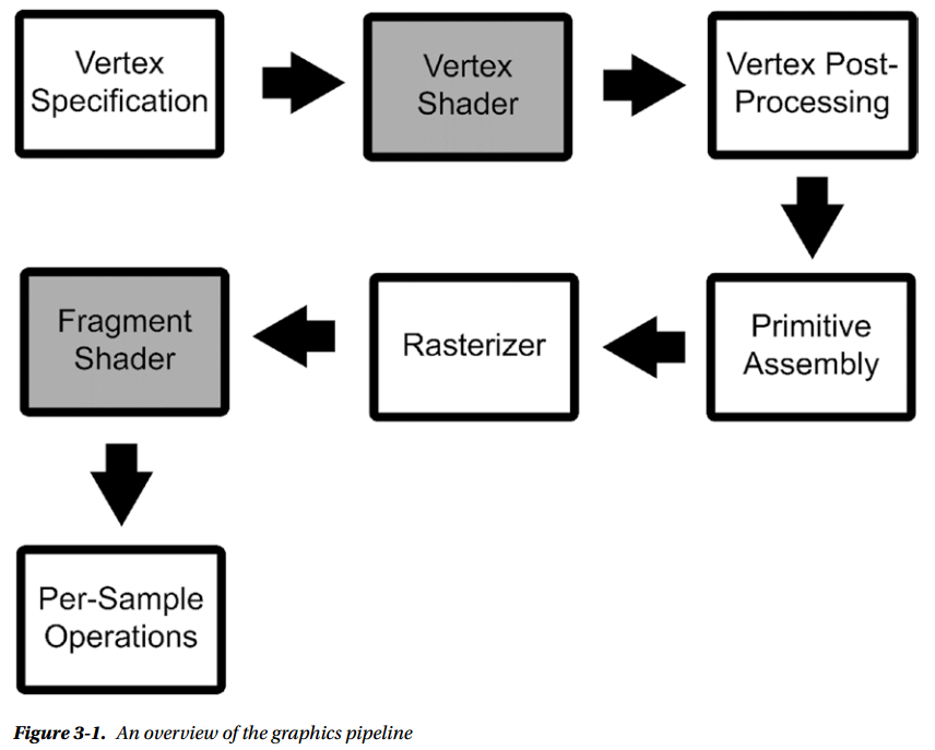
The stages of an example graphics pipeline are as follows:
The input assembly stage gathers data from the scene (meshes, textures, and materials) and organizes it to be used in the pipeline.
The vertex processing stage gets the vertices and their info from the previous stage and executes the vertex shader on each of them. The main objective of the vertex shader used to be obtaining 2D coordinates out of vertices. In more recent API versions, that is left to a different, later stage.
The vertex post-processing stage includes transformations between coordinate spaces and the clipping of primitives that are not going to end up on the screen.
The primitive assembly stage gathers the data output by the vertex processing stages in a primitive and prepares it to be sent to the next stage.
The rasterizer is not a programmable stage. It takes a triangle (three vertices and their data) and creates potential pixels (fragments) out of it. It also produces an interpolated version of the vertex attributes data for each of the fragments and a depth value.
The fragment shader stage runs the fragment shader on all the fragments that the rasterizer produces. In order to calculate the color of a pixel, multiple fragments may be necessary (e.g., antialiasing).
The output merger performs the visibility test that determine whether a fragment will be overwritten by a fragment in front of it. It also does other tests, such as the blending needed for transparency, and more.
This general overview is a mix of many different graphics pipelines, such as OpenGL and Direct3D 11. You might not find the same names in the specific one you want to use, but you’ll see very similar patterns.
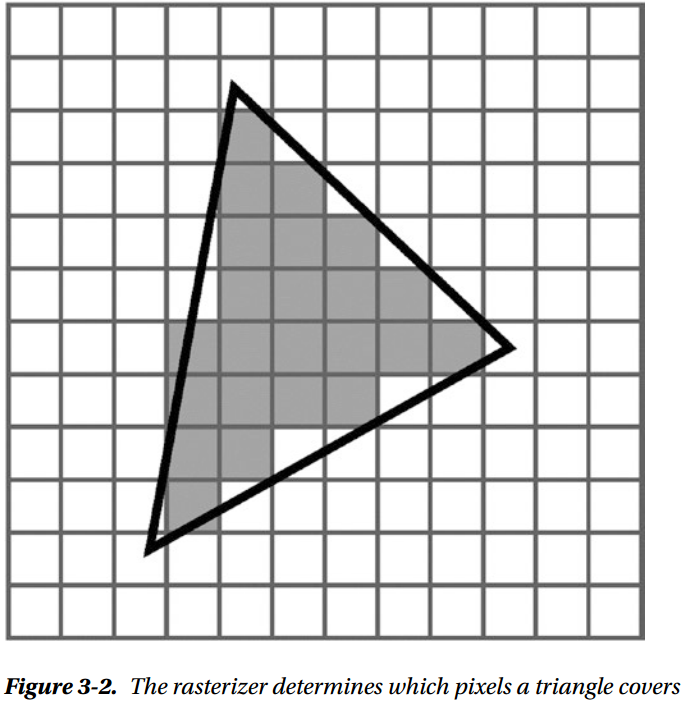
The Rasterizer
It determines which pixels in the final image the triangle covers. It also interpolates the different values that belong to each vertex (such as colors, UVs, or normals) over the pixels the triangle covers.
The Structure of an Unlit Shader
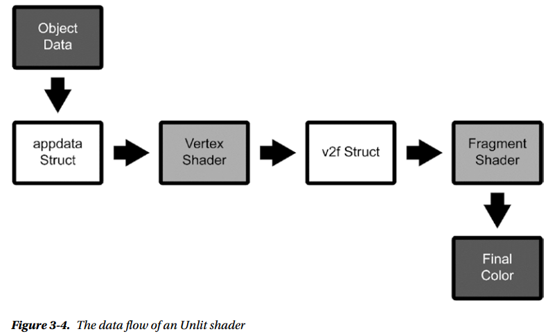
Vertex Data Structure
The first structure was appdata, which corresponds to the input assembly stage
struct appdata {
    float4 vertex: POSITION;
};
: POSITION is a shader semantic, which is a string attached to a shader data structure that conveys information about the intended use of a member. By adding members with a semantic to appdata, we tell the input assembly stage what data we want out of what is available.
In this case, we only asked for the vertex position, which is the bare minimum you’re always going to ask for. There is more data you can ask for, such as UV information to deal with texturing, or the vertex colors, should the model have them. The semantic and the data type must match. If you were to give it a single float for a POSITION semantic, the float4 value would be truncated silently to float.
The data type chooses the “shape” of the variable, but the semantic chooses what goes inside it. Many kinds of semantic can fill a float4, but if we were to mistake which semantic we want, the shader would break at runtime, likely in subtle ways. Subtle shader breakage is one of the worst issues to track down once your shaders get complex, so be careful.
This is the only way you can gather data that changes per vertex, but you can pass other data in from properties and global properties that doesn’t vary per vertex. OpenGL calls these per-vertex values, quite appropriately, varying, and the ones that you can pass globally, or a property in a shader, are called uniform.
Vertex Function
The next programmable stage is the vertex processing one, in which the vertex shader function is executed. It takes the appdata data structure (appdata) as an argument and returns the second type of data structure (v2f):
v2f vert(appdata v) {
    v2f o;
    o.vertex = UnityObjectToClipPos(v.vertex);
    return o;
};
This is the bare minimum that needs to be done in a vertex shader: transforming the coordinates of the vertex to a coordinate space that can be used by the rasterizer. You do that by using the UnityObjectToClipPos function.
Fragment Data Structure
Which members we include in the v2f data structure decides what data we can pass on from the vertex shader.
struct v2f {
    float4 vertex: SV_POSITION;
};
It’s very minimal and it only covers the 2D position of the vertex that was processed. We still need to get the semantic sort of right, but this data structure is less sensitive to mistakes. Keep in mind that semantics must not to be repeated. For example, you can’t assign the SV_POSITION semantic to a second member as well
Fragment Function
The next programmable stage is the fragment shading stage, where the fragment shader is executed on each fragment
float4 frag(v2f i): SV_Target {
    return _Color;
}
Actually, if you remember, that float4 wasn’t used anywhere in the code. But if you try to get rid of it, you’ll find that the shader doesn’t render anything at all. That value is used by the graphics pipeline, even if you don’t see it reflected in the shader code.
You may notice that the frag function has an output semantic, which we didn’t mention in the previous chapter. That is used for specific techniques that we are not going to cover in this book. You should stick with SV_Target, which means that it outputs one fragment color.
This simple shader shows you that the conversion from 3D scene space and 2D target render space works, because we can indeed render a 3D model into a 2D screen.
Adding Vertex Colors Support
Basically, we are adding one varying, one extra value attached to the vertex, which will need to be passed to the rasterizer, which will interpolate it.
Appdata Additions
When adding a member to appdata that is supposed to be filled with the vertex colors of the mesh (if the mesh has them), we need to pay attention to the name and semantic. The best bet is to use color as the name of the member and COLOR as semantic. Using only the COLOR semantic with a differently named variable might not work, depending on your platform
struct appdata
{
    float4 vertex: POSITION;
    float4 color: COLOR;
};
v2f Additions
struct v2f
{
    float4 vertex: SV_POSITION;
    float4 color: COLOR;
};
Assign the Color in the Vertex Function
It assigns whatever is in appdata’s color member to the v2f’s color member. The “magic” is here; it makes the vertex color data go through the rasterizer, which is going to interpolate the colors appropriately
v2f vert(appdata v)
{
    v2f o;
    o.vertex = UnityObjectToClipPos(v.vertex);
    o.color = v.color;
    return 0;
}
Use the Color in the Fragment Function
fixed4 frag(v2f i): SV_Target
{
    return i.color;
}
Final Result
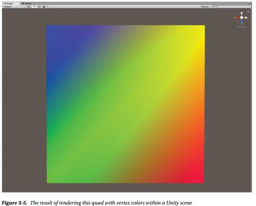
Shader "Custom/RasterizerTestShader"
{
    SubShader
    {
        Tags {"RenderType"="Opaque"}

        Pass
        {
            CGPROGRAM
#pragma vertex vert
#pragma fragment frag

#include "UnityCG.cginc"

            struct appdata
            {
                float4 vertex: POSITION;
                float4 color: COLOR;
            };

            struct v2f
            {
                float4 vertex: SV_POSITION;
                float4 color: COLOR;
            };

            v2f vert(appdata v)
            {
                v2f o;
                o.vertex = UnityObjectToClipPos(v.vertex);
                o.color = v.color;
                return o;
            }

            float4 frag(v2f i): SV_Target
            {
                return i.color;
            }

            ENDCG
        }
    }
}
Summary
Next
Chapter 4: Transforming Coordinate Spaces
Coordinate Spaces Who's Who
Object Space, World Space, Camera Space, Clip Space, Normalized Device Coordinates, and Screen Space
This is mostly the order in which they are used within the graphics pipeline
Object Space
Object Space is a 3D coordinate system that has its origin commonly set at the base, or center, of the mesh that is being sent to the rendering pipeline in the input assembly stage. The origin is likely the pivot point in the 3D modeling software that was used to model the mesh.
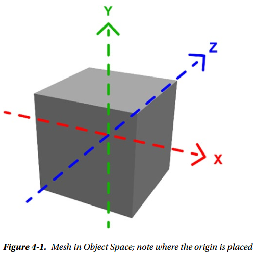
It can also be called Local Space or Model Space. However, in Autodesk Maya, Local Space is used to refer to a different coordinate system, so beware of possible confusion there. When the vertex position is stored into appdata, in order to be passed to the vertex shader, it is in Object Space.
World Space
In World Space, the frame of reference is not the single mesh, but the entire scene
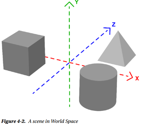
Where exactly the origin point falls in World Space depends on how you put the scene together. In Unity, this is the space in which your Unity scene lives, and the coordinates used in your GameObjects transforms should be in this coordinate space
Transformation Between Spaces
To transform between different coordinate spaces, matrix multiplications are normally used
Unity includes many built-in functions that implement the most commonly used transformations for some types of values, such as position, normals, light directions, etc. Here are some that will obtain a certain value in World Space
- float3 UnityObjectToWorldDir( in float3 dir ) takes a direction in Object Space and transforms it to a direction in World Space
- float3 UnityObjectToWorldNormal( in float3 norm ) takes a normal in Object Space and transforms it to a normal in World Space; useful for lighting calculations
- float3 UnityWorldSpaceViewDir( in float3 worldPos ) takes a vertex position in World Space and returns the view direction in World Space; useful for lighting calculations
- float3 UnityWorldSpaceLightDir( in float3 worldPos ) takes a vertex position in World Space and returns the light direction in World Space; useful for lighting calculations
Many functions that you can use to transform coordinates between spaces can be found in UnityShaderVariables.cginc, UnityShaderUtilities.cginc, and UnityCG.cginc
Here are some of the built-in Unity matrices for transformation from and to Object Space:
- unity_ObjectToWorld, which is a matrix that transforms from Object Space to World Space
- unity_WorldToObject, the inverse of the above, is a matrix that transforms from World Space to Object Space
As an example, let’s translate the vertex position from Object Space to World Space
float4 vertexWorld = mul(unity_ObjectToWorld, v.vertex);
Camera Space
Camera Space, also called Eye Space or View Space. This coordinate space contains the same scene as the World Space coordinate system, but from the point of view of the camera that you are rendering from.

Camera Space is needed, because it’s a necessary step to get to outputting Clip Space, but that is mostly taken care by the standard shader infrastructure.
There are a couple of built-in matrices for Camera Space:
- unity_WorldToCamera, which transforms from World Space to Camera Space
- unity_CameraToWorld, the inverse of the above, transforms from Camera Space to World Space
There is also one built-in function:
- float4 UnityViewToClipPos( in float3 pos ) transforms a position from View Space to Clip Space
Clip Space
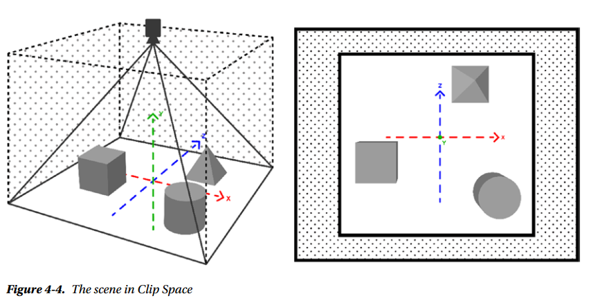
The vertex post-processing stage of the rendering pipeline includes clipping. Clipping removes any part of the primitives that are not within the boundaries of Clip Space. Clip Space coordinates range from -1 to 1
There’s one unintuitive bit of business going on here. You would expect the coordinate spaces we have listed up to now, Clip Space included, to have three coordinates—one for the x axis, one for the y axis, and one for the z axis. But in OpenGL (and other APIs), the 3D spaces we listed don’t use three coordinates; they use four: ( x, y, z, and w).
Where does this w coordinate come from, and why is it used? It turns out that there is an issue with using Cartesian spaces for 3D rendering: two parallel lines cannot meet each other, which makes it impossible to represent perspective. This additional coordinate is necessary for the workaround to this problem, which is called homogeneous coordinates. We keep around this additional coordinate w, and then, at the opportune moment (going from Clip Space to Normalized Device Coordinates), we divide all the others by it. Doing this, we can represent perspective.
So, Object, World, View, and Clip Space represent 3D spaces using these four coordinates. In all but Clip Space, w is 1. Then, w is changed with a number different from 1 by the matrix used to transform from View to Clip Space. That matrix is called the projection matrix in OpenGL. Then the w coordinate is used to determine whether a vertex should be clipped or not.
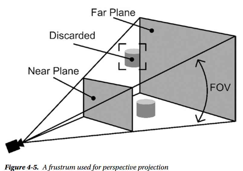
To set up the projection matrix, you need to use the information from the viewing volume (aka, the frustrum). The frustrum varies with what type of projection you want to use; common ones are perspective projection and orthographic projection.
In perspective projection, the frustrum is composed of a near and a far plane, where the near plane is smaller than the far one, because objects located farther from the camera will appear smaller in perspective. The field of view defines the proportion between the near and far plane. Changing it changes how much of the scene we’re going to render.
There are no built-in matrices for Clip Space, but there are some built-in functions for it:
- float4 UnityWorldToClipPos( in float3 pos ), which transforms a position from World Space to Clip Space
- float4 UnityViewToClipPos( in float3 pos ), which transforms a position from View Space to Clip Space
- float4 UnityObjectToClipPos(in float3 pos), which transforms a vertex position from Object Space to Clip Space
Normalized Device Coordinates
Next up are the Normalized Device Coordinates (NDC). This is a 2D space that is independent of the specific screen or image resolution. Coordinates in NDC are obtained by diving Clip coordinates by w, a process called perspective division. Again, NDC coordinates range from -1 to 1 in OpenGL. NDC uses three numbers instead of two, as you’d expect it to, but in this case the z coordinate is used for the depth buffer, rather than being a homogeneous coordinate.
Screen Space
Screen Space is the coordinate space of the 2D render target. That may be a screen buffer, or a separate render target, or an image. It is obtained by transforming and scaling NDC into viewport resolution. Finally, these screen coordinates of the vertices are passed to the rasterizer, which will use them to produce fragments.
Underneath Built-In Functions
v2f vert(appdata v)
{
    v2f o;
    o.vertex = UnityObjectToClipPos(v.vertex);
    o.color = v.color;
    return o;
}
UnityObjectToClipPos is a function that stands for mul(UNITY_MATRIX_MVP,*) which is a matrix multiplication, going from Object Space to Clip Space. Matrices are commonly combined by multiplying them by each other, so MVP stands for Model Matrix * View Matrix * Projection Matrix. In other words, we’re fast-forwarding from Object Space through World and View Space to get to Clip Space coordinates using just this one line.
Where to Find the Shader "Standard Library" Code

Summary
Next
Chapter 5: Your First Unity Lighting Shader
Lighting Shaders
A lighting shader includes all the calculations needed to simulate light hitting a surface. While most lighting shaders are based, at least loosely, on the rendering equation, a few years ago there wasn’t enough computational power in GPUs to do much more than very loose approximations of it. Until about 2010, when the physically based model started to trickle down from the movie rendering community, these were the terms we would use to refer to different parts of the lighting calculations:
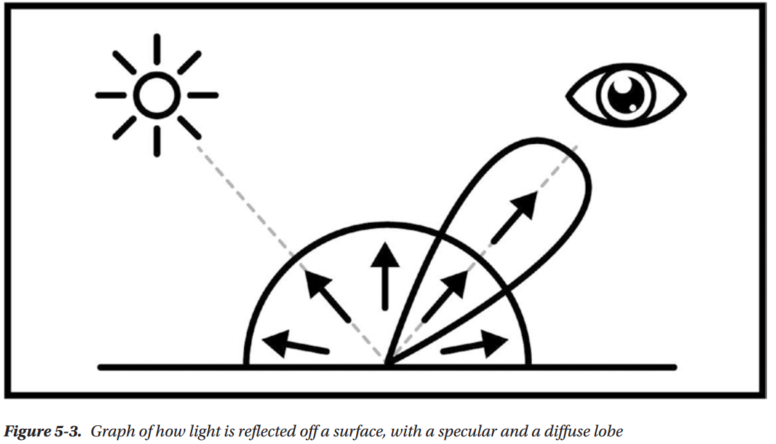
- Diffuse is the subset of a surface with irregular microfacets, that reflects light in many different directions
- Specular is the subset of the surface that has aligned microfacets, and reflects light in a few, similar directions
- Ambient is the minimum light intensity in the scene, so places where the direct light doesn’t reach won’t end up just black
These explanations are in terms of microfacet theory, which is something we can do now, since physically based rendering introduced it in real-time shading. But before that, diffuse and specular were quite hard to pin down precisely. That’s because in physical reality there is no such clean division between specular and diffuse. The variability in directions of the microfacets of a surface controls how smooth or rough that surface looks. A rougher surface will look more diffuse; a smoother surface will look more specular. Diffuse to specular is a continuum, not a binary choice.
What Is an Approximation
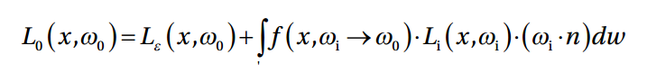
An approximation is a value or quantity that is nearly, but not exactly, correct. In our case, an approximation means an alternative way of calculating some parts of the rendering equation. Approximations can be less or more computationally intensive. As of yet, it’s impossible to calculate the rendering equation in real-time, due to the presence of an integral in it
meaning that the group of calculations after the is going to be repeated for each direction w in the hemisphere above the point on the surface called x . As you may suspect, each direction means a lot of directions. Solving this integral in real-time has so far eluded us, although we’re starting to see things like somewhat-real-time raytracing being implemented on GPUs.
Using a cheaper approximation may mean that your game can run at 60 fps, but it will also mean that you lost some potential rendering fidelity. Not all games focus on fidelity. Most of the time, graphics need only be good enough
Diffuse Approximation
Think of light hitting a surface, and then being reflected inany possible direction. Each reflection direction is equally probable
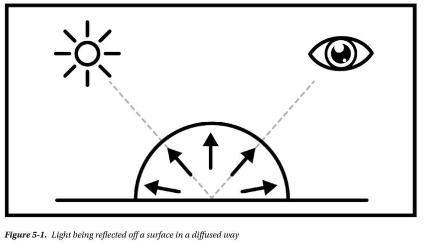
This approximation only concerns itself with the direction, color, and intensity of the light. It doesn’ttake into account the nature of the surface at the microscopic level. The objective is to determine how much light is hitting, and being reflected off, each pixel of the rendered model, without delving into a more detailed simulation. Imagine it as a function—you pass it the direction, color, and intensity of the light, as well as the unlit color of the surface, and it will give you the color of the final image at that point.
It’s possible to implement it in the vertex shader, which is computationally cheaper, since usually there are fewer vertices than pixels. This works because the rasterizer will interpolate the values, but as a side effect that creates pretty visible artifacts.
Specular Approximation
Think of a light hitting a surface and being reflected in just a few directions . At this level of approximation, specular light often appears as an almost white small circle. Again, this approximation is concerned only with the direction, color and intensity of the light.
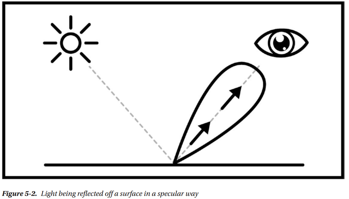
The fact that light is being reflected only in a few directions makes specular view-dependent, meaning that if your point of view moves, the specular term will change. Specular is trickier to simulate in lightmaps, because you need to bake the direction, and other information, in the lightmap as well
Diffuse and Specular Combined
Both diffuse and specular terms will show up in the same surface, most of the time. Metals have a lower diffuse component and a much higher specular one, but they still have a diffuse component. When you combine them, you have the typical graph commonly used to represent lighting calculations
Calculating Basic Lighting
Diffuse
That angle is called the angle of incidence, and the bigger it is, the less light the surface will receive from the ray. For angles bigger than 90 degrees, it won’t receive any light at all
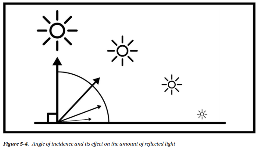
We talked about how the angle at which the light ray hits the surface is important. That angle is called the angle of incidence, and the bigger it is, the less light the surface will receive from the ray. For angles bigger than 90 degrees, it won’t receive any light at all

float brightness = cos( angle_of_incidence ) // brightness from the angle of incidence
float brightness = dot( normal, lightDir ) // brightness calculated from the Normal and
Light directions
float3 pixelColor = brightness * lightColor * surfaceColor // final value of the surface color
The result from this operation, multiplied by the color of the light and the color of the surface, will give you a crude but effective approximation of lighting. This basic diffuse is also known as Lambert, or Lambertian Reflectance:

Your First Lighting Unity Shader
Implementing a Diffuse Term
Tags { "LihgtMode" = "ForwardBase" }
This means that this pass will be used for the first light pass of the forward renderer. If we only have one ForwardBase pass, any lights after the first one won’t contribute to the final result. If we want them to, we need to add another pass and set its tags to the following:
Tags { "LightMode" = "ForwardAdd" }
#include "UnityLightingCommon.cginc"
UnityLightingCommon.cginc is a file that contains many useful variables and functions that can be used in lighting shaders. With this, the chores are over, so now we’re going to get into the meat of the implementation.
First, keep in mind that the Normal and Light directions need to be in one of the coordinate spaces. Thinking about it, we shouldn’t use Object Space, because the light is outside the model we’re rendering. The appropriate space to use for these lighting calculations is World Space.
First, we need to get the Normal information from the renderer; therefore, we need to add a slot for that normal to appdata, the data structure that contains the information we ask from the renderer
struct appdata
{
    float4 vertex: POSITION;
    float3 normal: NORMAL;
};
Notice that we’re also telling it that we want a normal by adding the NORMAL semantic to the declaration; otherwise, there’d be no way for the renderer to understand what we want
This vertex function will need to calculate the Normal direction in World Space. Fortunately, there is a handy function called UnityObjectToWorldNormal that takes the Object Space Normal direction we just passed to the vertex shader through appdata and translates it to World Space.
v2f vert (appdata v)
{
    v2f o;
    o.vertex = UnityObjectToClipPos(v.vertex);
    float3 worldNormal = UnityObjectToWorldNormal(v.normal); //calculate world normal
    o.worldNormal = worldNormal; //assign to output data structure
    return o;
}
Then we need to assign it to the output structure. To do that, we need to add that slot, using the TEXCOORD0 semantic to tell it to use a slot that fits a vector of three or four values.
struct v2f
{
    float4 vertex: SV_POSITION;
    float3 worldNormal: TEXTCOORD0;
};
Now we can use that information to calculate our Lambert diffuse. We can get the light color from the variable _LightColor0, which comes from the extra include file, and the World Space light position of the first light in the scene from the variable _WorldSpaceLightPos0.
In the fragment shader, we need to first normalize the worldNormal, as the result of a transform may not be a vector of magnitude 1. Then we calculate the dot product of normal and light direction, taking care not to let it become negative. That’s what the max function does.
float4 frag (v2f i) : SV_Target
{
    float3 normalDirection = normalize(i.worldNormal);
    float nl = max(0.0, dot(normalDirection,
    _WorldSpaceLightPos0.xyz));
    float4 diffuseTerm = nl * _Color * _LightColor0;
    return diffuseTerm;
}
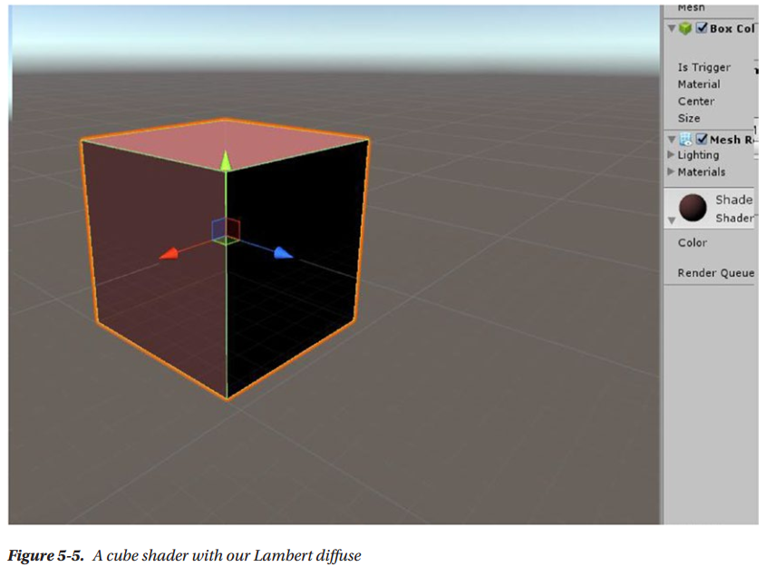
Shader "Custom/DiffuseShader"
{
    Properties
    {
        _Color("Color", Color) = (1,0,0,1)
    }
    SubShader
    {
        Tags { "LightMode" = "ForwardBase" }
        LOD 100

        Pass
        {
            CGPROGRAM
            #pragma vertex vert
            #pragma fragment frag
            #include "UnityCG.cginc"
            #include "UnityLightingCommon.cginc"
            struct appdata
            {
                float4 vertex : POSITION;
                float3 normal : NORMAL;
            };

            struct v2f
            {
                float4 vertex : SV_POSITION;
                float3 worldNormal : TEXCOORD0;
            };

            float4 _Color;
            v2f vert(appdata v)
            {
                v2f o;
                o.vertex = UnityObjectToClipPos(v.vertex);
                float3 worldNormal = UnityObjectToWorldNormal(v.normal);
                o.worldNormal = worldNormal;
                return o;
            }
            float4 frag(v2f i) : SV_Target
            {
                float3 normalDirection = normalize(i.worldNormal);
                float nl = max(0.0, dot(normalDirection, _WorldSpaceLightPos0.xyz));
                float4 diffuseTerm = nl * _Color * _LightColor0;
                return diffuseTerm;
            }
            ENDCG
        }
    }
}
Adding a Texture Property
In order to make the duck look better, we can add a texture property. Let’s add to the properties
DiffuseTex ("Texture", 2D) = "white" {}
Then, you need to add a slot for a texture coordinate in appdata
float2 uv : TEXCOORD0;
In v2f, since we are already using the TEXCOORD0 semantic for the world normal, we need to change that one to TEXCOORD1
float2 uv : TEXCOORD0;
This happens because we’re asking the GPU to give us interpolated texture UVs in that data structure.There is a finite number of texture interpolators we can access, and that’s different depending on the GPU in your machine. If you work with mobile GPUs and try to pass too many vectors in a data structure, you might encounter a compiler error
Let’s add the variables for the texture
sampler2D _DiffuseTex;
float4 _DiffuseTex_ST;
In the vertex function, we’re going to add this
o.uv = TRANSFORM_TEX(v.uv, _DiffuseTex);
This is the macro that scales and offsets texture coordinates. This way, any changes in the material properties regarding scales and offsets will be applied here. It’s also the reason why we’re declaring _DiffuseTex_ST, because it’s needed by TRANSFORM_TEX. Now we’re going to change the fragment function. We need to add a line to sample the texture, and then we need to use this texture with the diffuse calculations and the already existing _Color property
float4 frag (v2f i) : SV_Target
{
    float3 normalDirection = normalize(i.worldNormal);
    float4 tex = tex2D(_DiffuseTex, i.uv);
    float nl = max(_0.0, dot(normalDirection, _WorldSpaceLightPos0.xyz));
    float4 diffuseTerm = nl * _Color * tex * _LightColor0;
    return diffuseTerm;
}
We obtain the final color by multiplying the _Color with the texture sample color, and the dot product of normal and light directions
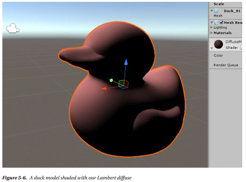
Shader "Custom/DiffuseShader"
{
    Properties
    {
        _DiffuseTex("Texture", 2D) = "white" {}
        _Color("Color", Color) = (1,0,0,1)
    }
    SubShader
    {
        Tags { "LightMode" = "ForwardBase" }
        LOD 100

        Pass
        {
            CGPROGRAM

            #pragma vertex vert
            #pragma fragment frag

            #include "UnityCG.cginc"
            #include "UnityLightingCommon.cginc"

            struct appdata
            {
                float4 vertex : POSITION;
                float3 normal : NORMAL;
                float2 uv: TEXCOORD0;
            };

            struct v2f
            {
                float4 vertex : SV_POSITION;
                float3 worldNormal : TEXCOORD1;
                float2 uv: TEXCOORD0;
            };

            sampler2D _DiffuseTex;
            float4 _DiffuseTex_ST;
            float4 _Color;

            v2f vert(appdata v)
            {
                v2f o;
                o.vertex = UnityObjectToClipPos(v.vertex);
                o.worldNormal = UnityObjectToWorldNormal(v.normal);
                o.uv = TRANSFORM_TEX(v.uv, _DiffuseTex);
                return o;
            }
            float4 frag(v2f i) : SV_Target
            {
                float3 normalDirection = normalize(i.worldNormal);
                float4 tex = tex2D(_DiffuseTex, i.uv);
                float nl = max(0.0, dot(normalDirection, _WorldSpaceLightPos0.xyz));
                float4 diffuseTerm = nl * _Color * tex * _LightColor0;
                return diffuseTerm;
            }
            ENDCG
        }
    }
}
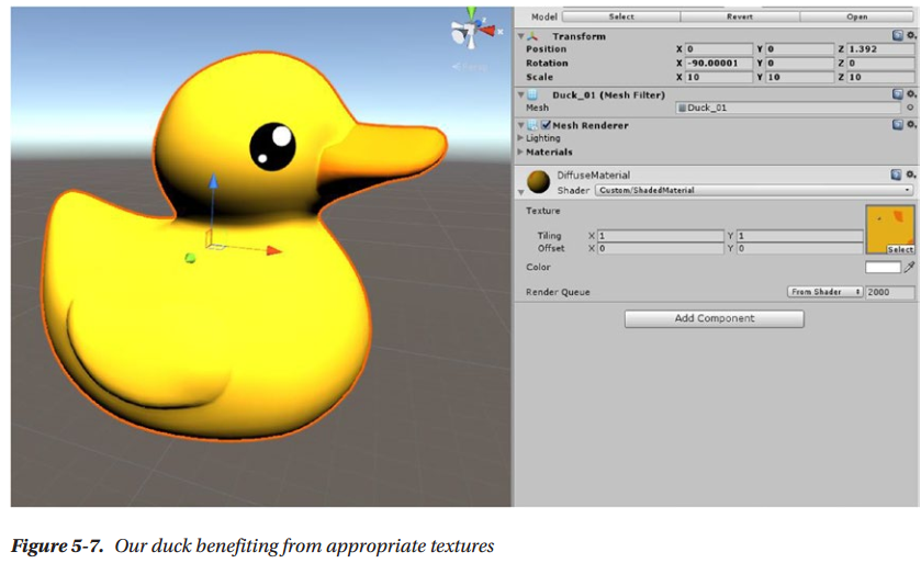
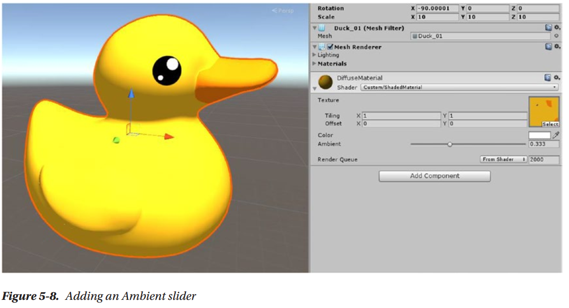
Adding an Ambient Value
As mentioned, an ambient is basically a cutoff value, under which we shouldn’t let our diffuse value drop. At the moment, it’s hard-coded as 0 in the fragment shader
float nl = max(0.0, dot(normalDirection, _WorldSpaceLightPos0.xyz));
However, we should probably add a property for it, so that we can change it without changing the code. This also introduces you to another type of property, ranges
_Name ("Description", Range (min, max)) = number
Shader "Custom/DiffuseShader"
{
    Properties
    {
        _DiffuseTex("Texture", 2D) = "white" {}
        _Color("Color", Color) = (1,0,0,1)
        _Ambient("Ambient", Range(0, 1)) = 0.25
    }
    SubShader
    {
        Tags { "LightMode" = "ForwardBase" }
        LOD 100

        Pass
        {
            CGPROGRAM

            #pragma vertex vert
            #pragma fragment frag

            #include "UnityCG.cginc"
            #include "UnityLightingCommon.cginc"

            struct appdata
            {
                float4 vertex : POSITION;
                float3 normal : NORMAL;
                float2 uv: TEXCOORD0;
            };

            struct v2f
            {
                float4 vertex : SV_POSITION;
                float3 worldNormal : TEXCOORD1;
                float2 uv: TEXCOORD0;
            };

            sampler2D _DiffuseTex;
            float4 _DiffuseTex_ST;
            float4 _Color;
            float _Ambient;

            v2f vert(appdata v)
            {
                v2f o;
                o.vertex = UnityObjectToClipPos(v.vertex);
                o.worldNormal = UnityObjectToWorldNormal(v.normal);
                o.uv = TRANSFORM_TEX(v.uv, _DiffuseTex);
                return o;
            }
            float4 frag(v2f i) : SV_Target
            {
                float3 normalDirection = normalize(i.worldNormal);
                float4 tex = tex2D(_DiffuseTex, i.uv);
                float nl = max(_Ambient, dot(normalDirection, _WorldSpaceLightPos0.xyz));
                float4 diffuseTerm = nl * _Color * tex * _LightColor0;
                return diffuseTerm;
            }
            ENDCG
        }
    }
}
Summary
Next
Chapter 6: Specular Implementation
Calculating Basic Lighting (Part II)
Specular
You will only see specular if your point of view happens to be lined up with the direction of the specular. That makes it view-dependent. You can bake diffuse lighting in standard lightmaps, but specular requires you to use some tricks in baking or calculate it in real-time.
One of the simplest formulation of specular we can use is called Phong:
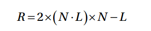
This is the reflection direction. It can be obtained by multiplying the dot product of Normal and Light directions with two and the Normal direction, and then subtracting the Light direction. In many shader languages there is a function for this, generally called reflect
float3 reflectionVector = reflect(-lightDir, normal);
float specDot = max(dot(reflectionVector, eyeDir), 0.0);
float spec = pow(specDot, specExponent);
To implement Phong, you need to first calculate the mirror reflection direction, then calculate the dot product of the reflection direction, and the view direction—as we said, specular is view-dependent. Then you elevate this value to the power of the exponent that you choose in the shader properties. That controls the specular intensity. You’ll see in a future chapter how this approach, while loosely based on physical reality, is actually violating many rules of physically based shading. When you correct it to conform to PBS principles, even a simple Phong feels much more realistic.
Your First Lighting Unity Shader (Part II)
Implementing a Specular
_SpecColor is the color of the specular and uses white as the default. _Shininess is the intensity of the specular and it is one number
Properties
{
    _DiffuseText("Texture" 2D) = "white" {}
    _Color("Color", Color) = (1, 0, 0, 1)
    _Ambient("Ambient", Range(0, 1)) = 0.25
    _SpecColor("Specular Material Color", Color) = (1, 1, 1, 1)
    _Shininess("Shininess", Float) = 10
}
Next, add a member to the v2f struct. You need to calculate an extra value in the vertex shader, and then pass them the fragment shader through v2f. That extra value is the world space vertex position, which we’re going to call vertexWorld
struct v2f
{
    float2 uv: TEXCOORD0;
    float4 vertexClip: SV_POSITION;
    float4 vertexWorld: TEXCOORD1;
    float3 worldNormal: TEXCOORD2;
};
You do this because you need to calculate the light direction in the fragment shader. You could do it in the vertex shader, and that would be called being vertex-lit. But the result, unsurprisingly, is going to look better if you do the lighting calculations in the fragment shader
v2f vert (appdata v)
{
    v2f o;
    o.vertexClip = UnityObjectToClipPos(v.vertex);
    o.vertexWorld = mul(unity_ObjectToWorld, v.vertex);
    o.uv = TRANSFORM_TEX(v.uv, _DiffuseTex);
    float3 worldNormal = UnityObjectToWorldNormal(v.normal);
    o.worldNormal = worldNormal;
    return o;
}
In this line, we’re using a matrix multiplication to transform the local space vertex position to the world space vertex position. unity_ObjectToWorld is the matrix you need for this transformation; it’s included in the standard library.
float3 normalDirection = normalize(i.worldNormal);
float3 viewDirection = normalize(UnityWorldSpaceViewDir(i.vertexWorld));
float3 lightDirection = normalize(UnityWorldSpaceLightDir(i.vertexWorld));
For best results, all the vectors need to be normalized after a transform. Depending on the situation, you might get away with avoiding that, but you risk bad artifacts in your lighting. Note that all those values are in the same coordinate space: World Space
float3 reflectionDirection = reflect(-lightDirection, normalDirection);
float3 specularDot = max(0.0, dot(viewDirection, reflectionDirection));
float3 specular = pow(specularDot, _Shininess);
First you find the reflectionDirection using the reflect function. You need to negate the lightDirection, so it goes from the object to the light. Then you calculate the dot product between viewDirection and reflectionDirection, which is the same sort of operation that you used to calculate how much light is being reflected off a surface in the diffuse term.
In the diffuse, it was between the normal and the light directions. Here, it’s between the mirror reflection direction and the view direction, because the specular term is view-dependent. Note that again, the dot product value cannot be negative. You can’t have negative light.
Then you need to add the specular to the final output. For the diffuse, you multiply it by the color of the surface. The equivalent of that for the specular is multiplying by the specular color.
float4 specularTerm = float4(specular, 1) * _SpecColor * _LightColor0;
float4 frag (v2f i) : SV_Target
{
    float3 normalDirection = normalize(i.worldNormal);
    float3 viewDirection = normalize(UnityWorldSpaceViewDir(i.vertexWorld));
    float3 lightDirection = normalize(UnityWorldSpaceLightDir(i.vertexWorld));

    // sample the texture
    float4 tex = tex2D(_DiffuseTex, i.uv);

    //Diffuse implementation (Lambert)
    float nl = max(0, dot(normalDirection, lightDirection));
    float4 diffuseTerm = nl * _Color * tex * _LightColor0;

    //Specular implementation (Phong)
    float3 reflectionDirection = reflect(-lightDirection, normalDirection);
    float3 specularDot = max(0.0, dot(viewDirection, reflectionDirection));
    float3 specular = pow(specularDot, _Shininess);
    float4 specularTerm = float4(specular, 1) * _SpecColor * _LightColor0;

    float4 finalColor = diffuseTerm + specularTerm;
    return finalColor;
}
Shader "Custom/SpecularShader"
{
    Properties
    {
        _DiffuseTex ("Texture", 2D) = "white" {}
        _Color ("Color", Color) = (1,0,0,1)
        _Ambient ("Ambient", Range (0, 1)) = 0.25
        _SpecColor ("Specular Material Color", Color) = (1,1,1,1)
        _Shininess ("Shininess", Float) = 10
    }
    SubShader
    {
        Tags { "LightMode" = "ForwardBase" }
        LOD 100

        Pass
        {
            CGPROGRAM
            #pragma vertex vert
            #pragma fragment frag

            #include "UnityCG.cginc"
            #include "UnityLightingCommon.cginc"

            struct appdata
            {
                float4 vertex : POSITION;
                float3 normal : NORMAL;
                float2 uv : TEXCOORD0;
            };

            struct v2f
            {
                float2 uv : TEXCOORD0;
                float4 vertexClip : SV_POSITION;
                float4 vertexWorld : TEXCOORD2;
                float3 worldNormal : TEXCOORD1;
            };

            sampler2D _DiffuseTex;
            float4 _DiffuseTex_ST;
            float4 _Color;
            float _Ambient;
              float _Shininess;

            v2f vert (appdata v)
            {
                v2f o;
                o.vertexClip = UnityObjectToClipPos(v.vertex);
                o.vertexWorld = mul(unity_ObjectToWorld, v.vertex);
                o.uv = TRANSFORM_TEX(v.uv, _DiffuseTex);
                float3 worldNormal = UnityObjectToWorldNormal(v.normal);
                o.worldNormal = worldNormal;
                return o;
            }

            float4 frag (v2f i) : SV_Target
            {
                float3 normalDirection = normalize(i.worldNormal);
                float3 viewDirection = normalize(UnityWorldSpaceViewDir(i.vertexWorld));
                float3 lightDirection = normalize(UnityWorldSpaceLightDir(i.vertexWorld));

                // sample the texture
                float4 tex = tex2D(_DiffuseTex, i.uv);

                //Diffuse implementation (Lambert)
                float nl = max(_Ambient, dot(normalDirection, lightDirection));
                float4 diffuseTerm = nl * _Color * tex * _LightColor0;
                //diff.rbg += ShadeSH9(half4(i.worldNormal,1));

                //Specular implementation (Phong)
                float3 reflectionDirection = reflect(-lightDirection, normalDirection);
                float3 specularDot = max(0.0, dot(viewDirection, reflectionDirection));
                float3 specular = pow(specularDot, _Shininess);
                float4 specularTerm = float4(specular, 1) * _SpecColor * _LightColor0;

                float4 finalColor = diffuseTerm + specularTerm;
                return finalColor;
            }
            ENDCG
        }
    }
}
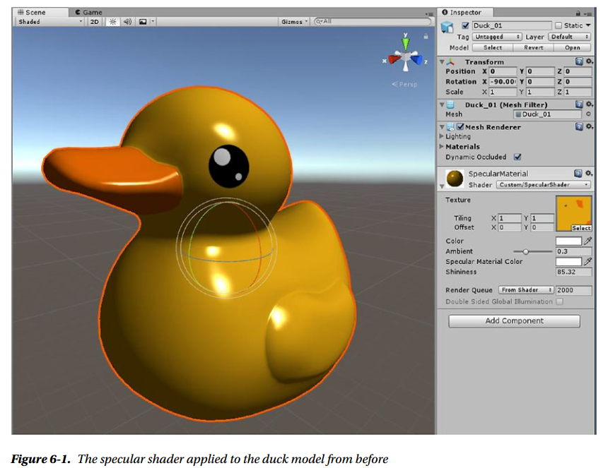
This concludes the introduction to the non-physically based Phong specular
Supporting More Than One Light
Pass
{
    Tags { "LightMode" = "ForwardBase" }
    CGPROGRAM
    #pragma vertex vert
    #pragma fragment frag
    #pragma multi_compile_fwdbase
ForwardAdd tells the compiler it should use this pass for any light after the first, and Blend One One sets up the blending mode. Blending modes are basically similar to the layer modes in Photoshop. We have different layers, rendered by different passes, and we want to blend them together in a way that makes sense. Keep in mind that the blending modes are much simpler than those available in Photoshop. The formula is Blend SrcFactor DstFactor; we used one for both factors which means that the colors are blended additively.
The pragmas are to take advantage of the automatic multi-compile system, which compiles all the variants of the shader needed for the specific pass to work
Pass
{
    Tags { "LightMode" = "ForwardAdd" }
    Blend One One
    CGPROGRAM
    #pragma vertex vert
    #pragma fragment frag
    #pragma multi_compile_fwdadd
This is already enough to have lights after the first influence the result. The finishing touch is to remove _Ambient as the minimum in the ForwardAdd pass, which means we won’t add the ambient twice or more
//Diffuse implementation (Lambert)
float nl = max(0.0, dot(normalDirection, lightDirection));
Shader "Custom/SpecularShaderForwardAdd"
{
    Properties
    {
        _DiffuseTex ("Texture", 2D) = "white" {}
        _Color ("Color", Color) = (1,0,0,1)
        _Ambient ("Ambient", Range (0, 1)) = 0.25
        _SpecColor ("Specular Material Color", Color) = (1,1,1,1)
        _Shininess ("Shininess", Float) = 10
    }
    SubShader
    {
        Pass
        {
            Tags { "LightMode" = "ForwardBase" }

            CGPROGRAM
            #pragma vertex vert
            #pragma fragment frag
            #pragma multi_compile_fwdbase

            #include "UnityCG.cginc"
            #include "UnityLightingCommon.cginc"

            struct appdata
            {
                float4 vertex : POSITION;
                float3 normal : NORMAL;
                float2 uv : TEXCOORD0;
            };

            struct v2f
            {
                float2 uv : TEXCOORD0;
                float4 vertexClip : SV_POSITION;
                float4 vertexWorld : TEXCOORD2;
                float3 worldNormal : TEXCOORD1;
            };

            sampler2D _DiffuseTex;
            float4 _DiffuseTex_ST;
            float4 _Color;
            float _Ambient;
              float _Shininess;

            v2f vert (appdata v)
            {
                v2f o;
                o.vertexClip = UnityObjectToClipPos(v.vertex);
                o.vertexWorld = mul(unity_ObjectToWorld, v.vertex);
                o.uv = TRANSFORM_TEX(v.uv, _DiffuseTex);
                float3 worldNormal = UnityObjectToWorldNormal(v.normal);
                o.worldNormal = worldNormal;
                return o;
            }

            float4 frag (v2f i) : SV_Target
            {
                float3 normalDirection = normalize(i.worldNormal);
                float3 viewDirection = normalize(UnityWorldSpaceViewDir(i.vertexWorld));
                float3 lightDirection = normalize(UnityWorldSpaceLightDir(i.vertexWorld));

                // sample the texture
                float4 tex = tex2D(_DiffuseTex, i.uv);

                //Diffuse implementation (Lambert)
                float nl = max(_Ambient, dot(normalDirection, lightDirection));
                float4 diffuseTerm = nl * _Color * tex * _LightColor0;
                //diff.rbg += ShadeSH9(half4(i.worldNormal,1));

                //Specular implementation (Phong)
                float3 reflectionDirection = reflect(-lightDirection, normalDirection);
                float3 specularDot = max(0.0, dot(viewDirection, reflectionDirection));
                float3 specular = pow(specularDot, _Shininess);
                float4 specularTerm = float4(specular, 1) * _SpecColor * _LightColor0;

                float4 finalColor = diffuseTerm + specularTerm;
                return finalColor;
            }
            ENDCG
        }
        Pass
        {
            Tags { "LightMode" = "ForwardAdd" }
            Blend One One

            CGPROGRAM
            #pragma vertex vert
            #pragma fragment frag
            #pragma multi_compile_fwdadd

            #include "UnityCG.cginc"
            #include "UnityLightingCommon.cginc"

            struct appdata
            {
                float4 vertex : POSITION;
                float3 normal : NORMAL;
                float2 uv : TEXCOORD0;
            };

            struct v2f
            {
                float2 uv : TEXCOORD0;
                float4 vertexClip : SV_POSITION;
                float4 vertexWorld : TEXCOORD2;
                float3 worldNormal : TEXCOORD1;
            };

            sampler2D _DiffuseTex;
            float4 _DiffuseTex_ST;
            float4 _Color;
            float _Ambient;
              float _Shininess;

            v2f vert (appdata v)
            {
                v2f o;
                o.vertexClip = UnityObjectToClipPos(v.vertex);
                o.vertexWorld = mul(unity_ObjectToWorld, v.vertex);
                o.uv = TRANSFORM_TEX(v.uv, _DiffuseTex);
                float3 worldNormal = UnityObjectToWorldNormal(v.normal);
                o.worldNormal = worldNormal;
                return o;
            }

            float4 frag (v2f i) : SV_Target
            {
                float3 normalDirection = normalize(i.worldNormal);
                float3 viewDirection = normalize(UnityWorldSpaceViewDir(i.vertexWorld));
                float3 lightDirection = normalize(UnityWorldSpaceLightDir(i.vertexWorld));

                // sample the texture
                float4 tex = tex2D(_DiffuseTex, i.uv);

                //Diffuse implementation (Lambert)
                float nl = max(0.0, dot(normalDirection, lightDirection));
                float4 diffuseTerm = nl * _Color * tex * _LightColor0;
                //diff.rbg += ShadeSH9(half4(i.worldNormal,1));

                //Specular implementation (Phong)
                float3 reflectionDirection = reflect(-lightDirection, normalDirection);
                float3 specularDot = max(0.0, dot(viewDirection, reflectionDirection));
                float3 specular = pow(specularDot, _Shininess);
                float4 specularTerm = float4(specular, 1) * _SpecColor * _LightColor0;

                float4 finalColor = diffuseTerm + specularTerm;
                return finalColor;
            }
            ENDCG
        }
    }
}
Summary
Next
Chapter 7: Surface Shaders
What Is a Surface Shader?
A Surface shader is a type of shader unique to Unity, which is meant to be used for shaders that calculate surface lighting models.
Their main advantage is that they hide a fair bit of boilerplate code.
The structure of Surface shaders differs from Unlit shaders. In Unlit shaders, we use two shader functions (vertex, and fragment), two data structures (one for the input to the vertex function, the other for the output), and if you want to support more than one light you need to write two passes, ForwardAdd and ForwardBase. In a Surface shader, the vertex function is optional, so you still use two data structures but they have different purposes, and you don’t specify the fragment function at all, but you have to write a surface
function instead. Also you can optionally write your own lighting model function.
The Default Surface Shader
Shader "Custom/SurfaceShader" {
    Properties {
        _Color ("Color", Color) = (1,1,1,1)
        _MainTex ("Albedo (RGB)", 2D) = "white" {}
        _Glossiness ("Smoothness", Range(0,1)) = 0.5
        _Metallic ("Metallic", Range(0,1)) = 0.0
    }
    SubShader {
        Tags { "RenderType"="Opaque" }
        LOD 200

        CGPROGRAM
        // Physically based Standard lighting model, and enable shadows on all light types
        #pragma surface surf Standard fullforwardshadows

        // Use shader model 3.0 target, to get nicer looking lighting
        #pragma target 3.0

        sampler2D _MainTex;

        struct Input {
            float2 uv_MainTex;
        };

        half _Glossiness;
        half _Metallic;
        fixed4 _Color;

        // Add instancing support for this shader. You need to check 'Enable Instancing' on materials that use the shader.
        // See https://docs.unity3d.com/Manual/GPUInstancing.html for more information about instancing.
        // #pragma instancing_options assumeuniformscaling
        UNITY_INSTANCING_CBUFFER_START(Props)
            // put more per-instance properties here
        UNITY_INSTANCING_CBUFFER_END

        void surf (Input IN, inout SurfaceOutputStandard o) {
            // Albedo comes from a texture tinted by color
            fixed4 c = tex2D (_MainTex, IN.uv_MainTex) * _Color;
            o.Albedo = c.rgb;
            // Metallic and smoothness come from slider variables
            o.Metallic = _Metallic;
            o.Smoothness = _Glossiness;
            o.Alpha = c.a;
        }
        ENDCG
    }
    FallBack "Diffuse"
}
Pragmas
#pragma surface surf Standard fullforwardshadows
surf is the surface function, Standard is the lighting model, and fullforwardshadows is an option.
If you want to use a vertex function different from the default one, you can. You can write your custom vertex function within the Surface shader, specifying the vertex input and output data structures (which usually are called appdata and v2f, for historical reasons, but you call them whatever you like), and finally pass it to the surf pragma this way
#pragma surface surf Lambert vertex:vert
surf is again the surface function, Lambert is a built-in lighting model, and vertex:vert specifies the vertex function.
New Data Structure
Let’s ignore for now the parts about instancing and examine the surface function. It takes a data structure called Input, which is included in this shader, and one called SurfaceOutputStandard, which has inout as a type qualifier. That means it’s an input, but also an output, and you won’t need two different data structures for that. This SurfaceOutputStandard data structure will then be sent to the lighting function (Standard, BlinnPhong, Lambert, or you can write a custom one).
The Input structure in this shader only includes the UVs, taking part of the role that was reserved for the vertex output function, v2f
struct Input {
    float2 uv_MainTex;
};
SurfaceOutputStandard comes from the usual include files, particularly from UnityPBSLighting.cginc
struct SurfaceOutputStandard
{
    fixed3 Albedo; // base (diffuse or specular) color
    fixed3 Normal; // tangent space normal, if written
    half3 Emission;
    half Metallic; // 0=non-metal, 1=metal
    half Smoothness; // 0=rough, 1=smooth
    half Occlusion; // occlusion (default 1)
    fixed Alpha; // alpha for transparencies
};
The objective of this data structure is to pass information to the lighting function.
The Surface Function
void surf (Input IN, inout SurfaceOutputStandard o) {
    fixed4 c = tex2D (_MainTex, IN.uv_MainTex) * _Color;
    o.Albedo = c.rgb;
    // Metallic and smoothness come from slider variables
    o.Metallic = _Metallic;
    o.Smoothness = _Glossiness;
    o.Alpha = c.a;
}
As you can see, in this default shader four of the seven members of the SurfaceOutputStandard data structure are being filled in, and some of those are used by most lighting models, while some others are specific to the Standard lighting model used by Unity
Albedo is the name used in Unity for the color of the surface, which generally comes from the diffuse texture. Alpha is not really used unless you’re drawing a transparent mesh. Normal takes data that comes from Normal maps, and Emission is used if the mesh is supposed to emit light. Everything else is specific to the Standard lighting model.
What's a Lighting Model?
The Standard lighting function is very complex, so let’s look at one we already are familiar with, the Lambert lighting function taken from Lighting.cginc (but liberally edited so it fits in one function).
inline fixed4 LightingLambert (SurfaceOutput s, UnityGI gi)
{
    fixed4 c;
    UnityLight light = gi.light;
    fixed diff = max (0, dot (s.Normal, light.dir));

    c.rgb = s.Albedo * light.color * diff;
    c.a = s.Alpha;

    #ifdef UNITY_LIGHT_FUNCTION_APPLY_INDIRECT
        c.rgb += s.Albedo * gi.indirect.diffuse;
    #endif

    return c;
}
This is a lighting model function. Any custom lighting models that you can write yourself would follow this same pattern. It returns a fixed4 and takes one SurfaceOutput and one UnityGI structure. SurfaceOutput is similar to SurfaceOutputStandard, it just has fewer members, because Lambert is a simpler lighting model. UnityGI is a data structure used to pass around the indirect light calculated by the global illumination system. Global Illumination is basically a much better way to solve the problem of calculating indirect light, which in the past chapter we crudely solved with a simple Ambient value.
You don’t need to worry about global illumination yet. The important member of UnityGI for this topic is light, which is another data structure, UnityLight. UnityLight includes the light direction and the light color. You should recognize the calculation we used in Chapter 5 to implement Lambert: the dot product and the multiplication with the light and surface colors.
A lighting function is supposed to simulate the behavior of light on a surface. To do that, as you’ve learned from the Diffuse and Specular approximations, it’s going to need some bits of information. Namely the light direction, the normal direction, the surface and light colors, and possibly the view direction.
SurfaceOutput and its cousin SurfaceOutputStandard both contain the normal and the color (albedo) of the surface as members. The light direction and color are obtained from the UnityGI data structure. In other words, a lighting function gets passed all the data needed to calculate lighting, either with the input data structure or by other arguments.
Lambert doesn’t need a view direction, but if it did, the function signature would be:
half4 Lighting<Name> (SurfaceOutput s, half3 viewDir, UnityGI gi);
Using these function signatures will make the compiler recognize your function as a lighting model function, and you’ll be able to use it in the surface pragma.
Data Flow of a Surface Shader
For now, be aware that the flow of data goes starts from the optional vertex function, for which you can make input and output data structures, or stick to those included in the standard library. Then it goes from the vertex function to the Input struct, which is passed to the surface function. In the surface function, you fill in a data structure that contains most of the data needed to calculate the lighting, which is generally named SurfaceOutput or similar. That struct is passed to the lighting function, which finally returns a color
Editing a Surface Shader
Add a Second Albedo Map
One of the most common tasks that using the Standard lighting model won’t solve is when you need more textures than it gives you
Properties {
    _Color ("Color", Color) = (1,1,1,1)
    _MainTex ("Albedo (RGB)", 2D) = "white" {}
    _SecondAlbedo ("Second Albedo (RGB)", 2D) = "white" {}
    _AlbedoLerp ("Albedo Lerp", Range(0,1)) = 0.5
    _Glossiness ("Smoothness", Range(0,1)) = 0.5
    _Metallic ("Metallic", Range(0,1)) = 0.0
}
You may think we need to add another set of UVs for the second texture to the Input struct, but if the texture has the same UVs (and it should, because it’s for the same model), you can recycle the same set of UVs for both
sampler2D _MainTex;
sampler2D _SecondAlbedo;
half _AlbedoLerp;
void surf (Input IN, inout SurfaceOutputStandard o) {
    fixed4 c = tex2D (_MainTex, IN.uv_MainTex);
    fixed4 secondAlbedo = tex2D (_SecondAlbedo, IN.uv_MainTex);
    o.Albedo = lerp(c, secondAlbedo, _AlbedoLerp) * _Color;
    // Metallic and smoothness come from slider variables
    o.Metallic = _Metallic;
    o.Smoothness = _Glossiness;
    o.Alpha = c.a;
}
// Upgrade NOTE: upgraded instancing buffer 'Props' to new syntax.

Shader "Custom/SurfaceShaderSecondAlbedo" {
    Properties {
        _Color ("Color", Color) = (1,1,1,1)
        _MainTex ("Albedo (RGB)", 2D) = "white" {}
        _SecondAlbedo ("Second Albedo (RGB)", 2D) = "white" {}
        _AlbedoLerp ("Albedo Lerp", Range(0,1)) = 0.5
        _Glossiness ("Smoothness", Range(0,1)) = 0.5
        _Metallic ("Metallic", Range(0,1)) = 0.0
    }
    SubShader {
        Tags { "RenderType"="Opaque" }
        LOD 200

        CGPROGRAM
        // Physically based Standard lighting model, and enable shadows on all light types
        #pragma surface surf Standard fullforwardshadows

        // Use shader model 3.0 target, to get nicer looking lighting
        #pragma target 3.0

        sampler2D _MainTex;
        sampler2D _SecondAlbedo;
        half _AlbedoLerp;

        struct Input {
            float2 uv_MainTex;
        };

        half _Glossiness;
        half _Metallic;
        fixed4 _Color;

        // Add instancing support for this shader. You need to check 'Enable Instancing' on materials that use the shader.
        // See https://docs.unity3d.com/Manual/GPUInstancing.html for more information about instancing.
        // #pragma instancing_options assumeuniformscaling
        UNITY_INSTANCING_BUFFER_START(Props)
            // put more per-instance properties here
        UNITY_INSTANCING_BUFFER_END(Props)

        void surf (Input IN, inout SurfaceOutputStandard o) {
            // Albedo comes from a texture tinted by color
            fixed4 c = tex2D (_MainTex, IN.uv_MainTex);
            fixed4 secondAlbedo = tex2D (_SecondAlbedo, IN.uv_MainTex);
            o.Albedo = lerp(c, secondAlbedo, _AlbedoLerp)  * _Color;
            // Metallic and smoothness come from slider variables
            o.Metallic = _Metallic;
            o.Smoothness = _Glossiness;
            o.Alpha = c.a;
        }
        ENDCG
    }
    FallBack "Diffuse"
}
Add a Normal Map
Another very common task is dealing with normal maps.
Properties {
    _Color ("Color", Color) = (1,1,1,1)
    _MainTex ("Albedo (RGB)", 2D) = "white" {}
    _NormalMap("Normal Map", 2D) = "bump" {}
    _Glossiness ("Smoothness", Range(0,1)) = 0.5
    _Metallic ("Metallic", Range(0,1)) = 0.0
}
sampler2D _NormalMap;

void surf (Input IN, inout SurfaceOutputStandard o) {
    fixed4 c = tex2D (_MainTex, IN.uv_MainTex) * _Color;
    o.Normal = UnpackNormal (tex2D (_NormalMap, IN.uv_MainTex));
    o.Albedo = c.rgb;
    // Metallic and smoothness come from slider variables
    o.Metallic = _Metallic;
    o.Smoothness = _Glossiness;
    o.Alpha = c.a;
}
What we’re doing with the UnpackNormal function here in a Surface shader would require two extra vertex shader output members (binormal and tangent in World Space) and another few lines in the fragment function, if we were to do this within an Unlit shader. So some effort is saved by using Surface shaders to deal with normal maps.
Shader "Custom/SurfaceShaderNormalMap" {
    Properties{
    _Color("Color", Color) = (1,1,1,1)
    _MainTex("Albedo (RGB)", 2D) = "white" {}
    _NormalMap("Normal Map", 2D) = "bump" {}
    _Glossiness("Smoothness", Range(0,1)) = 0.5
    _Metallic("Metallic", Range(0,1)) = 0.0
    }
        SubShader{
        Tags { "RenderType" = "Opaque" }
        LOD 200
        CGPROGRAM
        #pragma surface surf Standard fullforwardshadows
        #pragma target 3.0
        sampler2D _MainTex;
        sampler2D _NormalMap;
        struct Input {
        float2 uv_MainTex;
        };

        half _Glossiness;
        half _Metallic;
        fixed4 _Color;
        UNITY_INSTANCING_CBUFFER_START(Props)
        UNITY_INSTANCING_CBUFFER_END
        void surf(Input IN, inout SurfaceOutputStandard o) {
        fixed4 c = tex2D(_MainTex, IN.uv_MainTex) * _Color;
        o.Normal = UnpackNormal(tex2D(_NormalMap, IN.uv_MainTex));
        o.Albedo = c.rgb;
        o.Metallic = _Metallic;
        o.Smoothness = _Glossiness;
        o.Alpha = c.a;
        }
        ENDCG
    }
        FallBack "Diffuse"
}
Making Sure Shadow Work
You might have noticed that all the shaders have a fallback value that we haven’t mentioned yet. The fallback is the name of a different shader that’s going to be used to render the shadows for meshes that use the shader. If your fallback shader is missing or broken, the shadows for the mesh will also be broken.
If the shadows of some of your meshes are missing, this is one of the things you should check.
Use Different Built-In Lighting Models
We’ve been using the Standard lighting model, but we can easily switch to a different one if we want to. Let’s use the BlinnPhong one instead. To do that, first change the surf pragma to this:
#pragma surface surf BlinnPhong fullforwardshadows
The BlinnPhong light function takes the SurfaceOutput data structure, instead of the SurfaceOutputStandard, so let’s change the signature of the surf function to this:
void surf (Input IN, inout SurfaceOutput o) {
BlinnPhong has no concept of glossiness and metallic, so we should remove them from the properties, the variable declarations, and the surf function.
Then we need to add as properties the Gloss and Specular values that the BlinnPhong lighting model function uses
inline fixed4 UnityPhongLight (SurfaceOutput s, half3 viewDir, UnityLight light)
{
    half3 h = normalize (light.dir + viewDir);
    fixed diff = max (0, dot (s.Normal, light.dir));
    float nh = max (0, dot (s.Normal, h));
    float spec = pow (nh, s.Specular*128.0) * s.Gloss;
    fixed4 c;
    c.rgb = s.Albedo * light.color * diff + light.color * _SpecColor.rgb * spec;
    c.a = s.Alpha;
    return c;
}
Specular, SpecColor, and Gloss are used in the BlinnPhong implementation. Traditionally in Unity the alpha of the albedo texture has been use to provide the gloss, and the specular has been declared as shininess in the properties. The SpecColor also needs to be added to the properties, but not to the declarations, as that happens by default
Shader "Custom/SurfaceShaderBlinnPhong" {
    Properties{
    _Color("Color", Color) = (1,1,1,1)
    _MainTex("Albedo (RGB)", 2D) = "white" {}
    _SpecColor("Specular Material Color", Color) = (1,1,1,1)
    _Shininess("Shininess", Range(0.03, 1)) = 0.078125
    }
        SubShader{
        Tags { "RenderType" = "Opaque" }
        LOD 200
        CGPROGRAM
        #pragma surface surf BlinnPhong fullforwardshadows
        #pragma target 3.0
        sampler2D _MainTex;
        float _Shininess;
        struct Input {
        float2 uv_MainTex;
        };
        fixed4 _Color;
        UNITY_INSTANCING_CBUFFER_START(Props)
            // put more per-instance properties here
            UNITY_INSTANCING_CBUFFER_END
            void surf(Input IN, inout SurfaceOutput o) {
            fixed4 c = tex2D(_MainTex, IN.uv_MainTex) * _Color;
            o.Albedo = c.rgb;
            o.Specular = _Shininess;
            o.Gloss = c.a;
            o.Alpha = 1.0f;
            }
            ENDCG
    }
        FallBack "Diffuse"
}
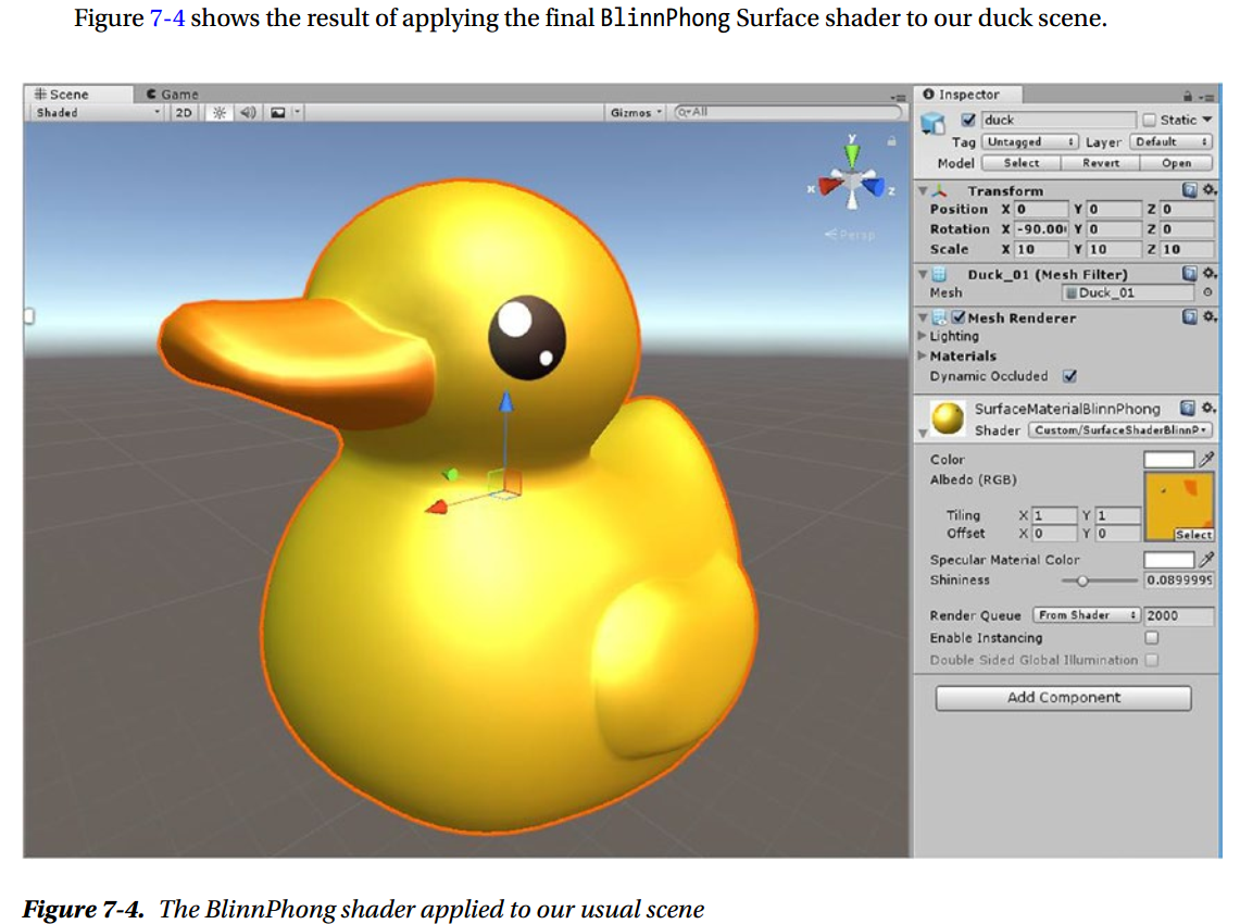
Writing a Custom Lighting Model
Lighting Model Function Signatures
As mentioned earlier, custom lighting model functions have to conform to one of a few possible signatures. There are four of them. Two of them are used in the Forward renderer, one is diffuse only, and one is viewdependent, so it can be used for speculars. Here is the diffuse one
half4 Lighting<Name> (SurfaceOutput s, UnityGI gi);
Here is the view-dependent one
half4 Lighting<Name> (SurfaceOutput s, half3 viewDir, UnityGI gi);
The other two are for the current deferred renderer and the legacy deferred renderer. We’re not going to cover deferred rendering in this book, because using a deferred renderer limits the data we can use in our shaders, and the more interesting lighting models require extra data that might not be available. All the principles you’re learning will work with deferred renderers anyway.
Here are the two function signatures used by the deferred renderers
half4 Lighting<Name>_Deferred (SurfaceOutput s, UnityGI gi, out half4 outDiffuseOcclusion, out half4 outSpecSmoothness, out half4 outNormal);
half4 Lighting<Name>_PrePass (SurfaceOutput s, half4 light);
We’re not going to use them, but it’s good to be able to recognize them.
The SurfaceOutput Data Structure
Phong is definitely view-depended, hence we need to use the second type signature
struct SurfaceOutput {
    fixed3 Albedo;
    fixed3 Normal;
    fixed3 Emission;
    half Specular;
    fixed Gloss;
    fixed Alpha;
};
We’re not going to need Emission (only used when the object is supposed to emit light). The Normal that we get from this data structure is already in World Space, and so are the light direction and the viewDir that we get from the function signature.
The Surface Function
Properties Block
The Custom Lighting Function
Summary
Next
Chapter 8: What Is Physically Based Shading?
Physically based shading is similar to shading as we used to do before, but now the lighting calculations are based on the physics of light with some precision
Light Is an Electromagnetic Wave
In general, when a surface’s irregularities are larger than the width of the light’s wavelength, it’s safe to not worry about the nature of light as a wave. Most of the behaviors that we are interested in can be explained from a higher level of abstraction, by thinking of light as rays.
Microfacet Theory Overview
Refraction and Other Beats
Fresnel Reflectance
How to Measure Light
Solid Angle
Power
Irradiance
Radiance
How to Represent a Material
Bidirectional Reflectance Distribution Function (BRDF)
Microfacet Theory
The Rendering Equation (Part II)
Hacks Real-Time Rendering Needs
HDR and Tone Mapping
Linear Color Space
Why Is Physically Based Shading Useful?
Summary
Next
Chapter 9: Making a Shader Physically Based
Analyzing Phong
Checking for Positivity
Checking for Reciprocity
Checking for Energy Conservation
The Modified Phong
Summary
Next
Chapter 10: Post-Processing Effects
How Post-Processing Effects Work
Why Post-Processing Effects Are Useful
Setting Up a Post Effect
HDR and Linear Setup
Script Setup
Conversion to Linear
RenderTextures Brief Overview
A Simple Tone Mapper
Post-Processing Stack v1
Post-Processing Stack v2
Summary
Next
Chapter 11: BRDFs Who's Who
BRDF Explorer
BRDF Parameterizations
Reading BRDF Explorer's Output
Phong
MERL Database
Comparing BRDFs
An Incomplete List of BRDFs Used in Real-Time Rendering
Summary
Next
Chapter 12: Implementing a BRDF
Which BRDF to Implement?
Finding References
CookTorrance
Disney
Starting from the Paper
CookTorrance (or Microfacet) BRDF
Disney BRDF
Implementation
Properties
Custom Light Function Implementation
Utility Functions
CookTorrance Implementation
Disney Diffuse
Another Implementation of the Disney Diffuse
Putting It All Together
Summary
Next
Chapter 13: Hooking Into the Standard Shader
Reverse-Engineering the Standard Shader
Shader Keywords
Standard Shader Structure
Chasing Down Shader Keywords
Implementing the Standard Shader Substitute
Summary
Next
Chapter 14: Implementing Advanced Techniques
Where to Find Techniques
Implementing Translucency
Properties
Implementation
Real-Time Reflections
What Is a Cubemap
What Are Reflection Probes
Evaluating a Cubemap
Cubemap Processing Programs
Summary
Next
Chapter 15: Making Shaders Artists Will Use
The UX of the Disney BRDF
Typical Problem #1: Too Many Settings
Typical Problem #2: The Effect of a Setting Is Unclear
Typical Problem #3: Settings Dependencies
Typical Problem #4: Unclear Compacting of Textures
Typical Problem #5: Strange Ranges
Positive Example: Disney BRDF in Blender
Summary
Next
Chapter 16: Complexity and Ubershaders
What Is an Ubershader?
The Standard Shader
What Causes Complexity in Shaders?
Ubershader Gotchas
Ubershader Advantages
Summary
Next
Chapter 17: When Shading Goes Wrong
Common Tricks
Debugging Tools
Looking at the Generated Shader Code
Performance Profiling
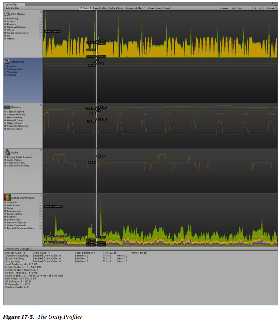
The Profiler can analyze performance in many subsystems of your game, but for the shaders you’re mainly going to care about the Rendering and the Global Illumination parts. Let’s look at some of the information you can get out of the Rendering Profiler:
Number of batches: Unity attempts to combine as many objects as possible, to minimize changes in the rendering settings. In the details, batches are broken down by type (Static, Dynamic, and GPU Instancing). Fewer is better.
Number of drawcalls: A drawcall is a call to the graphics API, where object data is sent to be rendered. Fewer is better.
Number of SetPass calls: SetPass calls are information sent by the CPU to the GPU. Fewer is better.
Number of triangles/vertices: As it says on the tin. It can help you keep an eye on spikes in on-screen primitives.
How much VRAM is being used.
RenderTexture number, memory used, and number of switches: RenderTextures are used in post processing, and you can also use them to process images on the GPU. If you have many active ones, they may eat up most of your VRAM.
Number of shadow casters.
Number and size of sent vertex buffer objects.
In general, you want to keep the numbers of all these items as small as possible, but how many you can afford really depends on the platform you’re targeting. Some of them may have a more dramatic effect than others. For example, mobile game development used to be very drawcall-sensitive, although it’s somewhat less so now.
One key issue to determine to optimize your game is whether your game is CPU- or GPU-bound, because they require different interventions. In the CPU Usage part of the Unity Profiler, all tasks executed for each frame are listed, with timings in milliseconds, and what percentage of the frame time they take up. You can drill down within Camera.Render until you get to Render.Mesh. You might want to create a test scene with just your shader, which will make it easier to figure out what it’s doing, but that may also backfire because some performance problems arise only within the context of a larger scene and then disappear in a simpler scene.
If you are GPU-bound and you have determined that one of your shaders is too slow, it’s time to dig out the frame-specific tools.
Keep in mind that not all shader debuggers give you useful information about the performance of your shader. In RenderDoc you can get timings per single drawcall by choosing the Time Durations for the Drawcalls option (a clock icon) within the Event Browser toolbar. In some other tools, you can only get frame percentage, which is not as useful, and still in others there are no timings at all. You need to spend some time to get to know the tools available for your use case and learn to get as much as possible out of them.
If you think you are using too many drawcalls, you should make sure you’re helping Unity to batch your meshes together as much as possible. For example, set every GameObject that isn’t supposed to move to static, and use the same material for as many meshes as possible, as meshes that use different materials can’t be batched.
Summary
Next
Chapter 18: Keeping Up with the Industry
Conferences
Books
Online Communities
Web Sites
Social Media
Conclusion